Lesson 01: Digital Systems and Number Systems
1.1 Digital Systems
What are Digital Systems?
Imagine a world where information exists not as continuous variations (like sound waves) but as distinct, discrete values: 0s and 1s. This binary language forms the heart of digital systems, which process and manipulate information using these fundamental units. From computers and smartphones to complex industrial controllers, countless systems rely on the principles of digital logic.
- Definition: Digital systems are electronic circuits manipulating discrete (digital) signals, typically represented as binary digits (0 and 1).
- Key Components: Digital systems consist of various components, including logic gates, flip-flops, registers, and more complex modules like arithmetic logic units (ALUs) and memory.
Basic Logical Values
- 0 (False): Represents the absence of voltage or signal, often interpreted as "low" or "off." Imagine a light switch: 0 corresponds to the light being off.
- 1 (True): Represents the presence of voltage or signal, often interpreted as "high" or "on." In our light switch analogy, 1 signifies the light being on.
Extended Logical Values
- X (Don't Care): Represents an unknown or indeterminate state. It indicates that the value of the signal is neither definitely 0 nor definitely 1.
- Z (High Impedance): This value applies specifically to outputs, indicating a state where the output pin offers no active drive but presents a high-impedance state. Imagine a wire disconnected from a circuit; it doesn't actively pull the voltage up or down, resulting in a "Z" state.
Building Blocks of Digital Systems
- Number Systems: Information in digital systems is represented using different number systems, like binary (base-2), decimal (base-10), hexadecimal (base-16), etc. Each system has its advantages and applications. Converting between them is crucial for understanding data flow and communication.
- Boolean Algebra: This mathematical system provides the tools to analyze, simplify, and optimize digital circuits. By expressing logic gates and circuits as Boolean expressions, we can manipulate them algebraically, leading to more efficient designs.
- Logic Gates: These are the fundamental building blocks that perform basic operations like AND, OR, NOT, and more. Think of them as tiny decision-makers, processing binary inputs and producing binary outputs based on their pre-defined logic. Imagine an AND gate acting like a strict bouncer: both inputs must be 1 for it to allow a 1 as output.
- Combinational Circuits: By connecting logic gates in specific arrangements, we create circuits that perform specific functions. Consider adding two binary numbers: a series of AND, OR, and XOR gates would work together to deliver the correct sum.
- Sequential Circuits: These circuits incorporate memory elements like flip-flops, allowing them to "remember" past inputs and influence future outputs. Imagine a traffic light controller: flip-flops hold the current state (red, yellow, green) and change based on internal logic and external signals.
1.2 Numbers and Number Systems
Number and Number Systems
A number system is a way to represent numbers.
How do we keep track of quantities, from eggs in a carton to stars in the sky? Number systems provide the answer!
Counting with Our Fingers and Beyond
Humans naturally love the number 10, likely because we have 10 fingers to help us count. This led to the development of the base-10 or decimal system, where each digit's position holds a value 10 times greater than the position to its right.
But 10 Isn't the Only Option!
Believe it or not, we actually use different number systems in our everyday lives:
- The base-60 system: This ancient counting method is still prevalent in measuring time, with 60 seconds making a minute and 60 minutes constituting an hour.
- The base-24 system: This is primarily used to tell time, dividing a day into 24 hours.
- The base-12 system: Commonly used in commerce and daily life, where a dozen represents twelve units of any item.
Each Base Has Its Own Rules
- In any base system, the available digits range from 0 to one less than the base. So, base-10 uses digits 0-9, base-60 uses 0-59, and so on.
- The position of each digit determines its value, just like in the base-10 number system.
Figure 1.1: Ten fingers on two hands, the possible starting point of the decimal counting
If humans had 6 fingers on their hands, would we be using the Senary system (also known as heximal or Seximal) of numbers?
Base-r Numbers to Decimal
To convert any base-r number to decimal:
- Expand base-r number using the positional scheme
- Perform computation using decimal arithmetic
Base-r system to decimal system:
- Determine the positional value of each digit (this depends on the position of the digit and the base of the number system)
- Multiply the obtained positional values (in step 1) by the digits in the corresponding positions.
- Sum the products calculated in Step 2. The total is the equivalent value in decimal.
Decimals to Base-r Number
Use the Radix Divide Method
The equation for decimal to base-r number:
Integral Part
- Divide (integral part) by the base- r number:

- Take the remainder as a coefficient
- Take the quotient and repeat the division, until the quotient is equal to zero

Fractional Part
- Multiply the number by the base- r number

- Take the integer (either 0 or 1) as a coefficient
- Take the resultant fraction and repeat the multiplication

In a digital system, each digit (bit, wire) has only two possible values: 0 or 1. It is called a Binary or base-2 number system. If there is a long binary number, for example (101110100101)binary, it is not suitable for humans to remember and is easily confused. One good way to reduce the length of the binary numbers is by grouping consecutive binary digits into groups of another number system. Therefore, we use Octal (a base-8 number system) and Hexadecimal (a base-16 number system) to represent a binary number in the digital system.
In mathematics, a 「base」 or a 「radix」 is the number of different digits or combination of digits and letters that a system of counting uses to represent numbers. ~Wiki~
Decimal
Decimal
Characteristics of the decimal number system are as follows:
- Also called denary
- Base-10
- Uses decimal digits: {0, 1, 2, 3, 4, 5, 6, 7, 8, 9}
- Positional System — position gives power to the base
- Example:
3845.2 = (3 x 10³) + (8 x 10²) + (4 x 101) + (5 x 100) + (2 x 10⁻¹) - Positions: …5 4 3 2 1 0 . -1 -2 -3 …
The base-10 system is a Positional Number System. it means each digit has a different value according to its position. For example: 255 is (2 x 100) + (5 x 10) + (5 x 1). There are a lot of other numeral systems that do not work that way. One of the most famous is Roman numerals, which is not really a positional system. In the Roman number system, The X stands for 10, the V stands for 5, and the I is a one. Twenty-seven in Roman numerals is XXVII ; it is 10 + 10 + 5 + 1 + 1 = 27 in decimal.
Binary
Binary
All the information is stored in a computer using digital signals that translate to binary numbers. A single bit can represent two possible states: on (1) or off (0).
Characteristics of the binary number system are as follows:
- Base-2
- Digits: {0, 1}
- Binary Digits are called bits
- Positional system
- Example:
1101.12 = (1 x 23) + (1 x 22) + (0 x 21) + (1 x 20) + (1 x 2-1)
Octal
Octal
Characteristics of the binary number system are as follows:
- Base-8
- Digits: {0, 1, 2, 3, 4, 5, 6, 7}
- A group of 3 binary digits can be used to represent each octal digit
- Positional system
- Example:
3578 = (3 x 82) + (5 x 81) + (7 x 80)
Hexadecimal
Hexadecimal
Characteristics of the hexadecimal number system are as follows:
- Base-16
- Digits: {0, 1, 2, 3, 4, 5, 6, 7, 8, 9, A, B, C, D, E, F}
- Groups of 4 bits represent each base 16 digit
- Positional system
- Example:
1F416 = (1 x 162) + (F x 161) + (4 x 160)
BCD
BCD
BCD (Binary Coded Decimal) is a decimal number system with a 4-bit binary number representing each decimal digit.
Do not get confused; BCD is not the same as hexadecimal. The hexadecimal also uses a 4-bit binary to represent one hex digit. Each hex digit is valid up to (F)16, representing binary (1111)2. But the one decimal digit is only up to 9 binary (1001)2. This means that the 4-bit binary can represent 16 numbers (24); in the BCD number system, the six binary codes from (1010)2 (decimal 10) to (1111)2 (decimal 15) are not used.
The main advantage of BCD is that it allows easy conversion between decimal and binary forms. However, the disadvantage is that the BCD code is wasteful as the states between (1010)2 and (1111)2 are not used.
For example, give the BCD representation for the decimal numbers 90 and 873.
The BCD representation of the number 90 is written as follows:
(90)10 = (1001 0000)BCD
For the number 873:
(873)10 = (1000 0111 0011)BCD
Points to Note:
- BCD is More Space Consuming: Each decimal digit is represented by four binary digits in BCD, which makes it less space-efficient than pure binary representation.
- BCD is Easier for Human Interpretation: BCD is closer to the decimal system and is often easier for humans to read and interpret than binary, which is why it is used in certain applications like digital clocks and calculators.
- Use in Digital Systems: BCD is frequently used in digital systems where a decimal display or decimal arithmetic is required.
Gray Code
Gray Code
A Gray Code encodes numbers so that adjacent numbers have one single digit differing by 1. Frank Gray invented this coding technique; thus, it is named so. The term gray code often refers to a "reflected" code, specifically the binary reflected Gray code.
Gray Code is a non-weighted code that does not ascribe a specific weight to each bit position. It is not used for arithmetic calculations.
Gray code is used in Karnaugh maps and the design of logic circuits. They also find application in rotary encoders, where the predisposition to errors increases with the number of bits that change logical states between two consecutive positions.
Gray Code Advantage:
- It can be used to minimize a logic circuit.
- It minimizes error while converting analog to digital signals.
Gray Code Disadvantage:
- It is not suitable for arithmetic operations.
- It is limited to a few practical applications.
ASCII Code
ASCII Code
ASCII code (American Standard Code for Information Interchange) has seven bits, representing 27 = 128 symbols.
Table 1: ASCII Table
| Dec | Hex | Char | Dec | Hex | Char | Dec | Hex | Char | Dec | Hex | Char | |
|---|---|---|---|---|---|---|---|---|---|---|---|---|
| 0 | 0x00 | NULL | null | 32 | 0x20 | SP | 64 | 0x40 | @ | 96 | 0x60 | ` |
| 1 | 0x01 | SOH | Start of heading | 33 | 0x21 | ! | 65 | 0x41 | A | 97 | 0x61 | a |
| 2 | 0x02 | STX | Start of text | 34 | 0x22 | " | 66 | 0x42 | B | 98 | 0x62 | b |
| 3 | 0x03 | ETX | End of text | 35 | 0x23 | # | 67 | 0x43 | C | 99 | 0x63 | c |
| 4 | 0x04 | EOT | End of transmission | 36 | 0x24 | $ | 68 | 0x44 | D | 100 | 0x64 | d |
| 5 | 0x05 | ENQ | Inquiry | 37 | 0x25 | % | 69 | 0x45 | E | 101 | 0x65 | e |
| 6 | 0x06 | ACK | Acknowledge | 38 | 0x26 | & | 70 | 0x46 | F | 102 | 0x66 | f |
| 7 | 0x07 | BELL | Bell | 39 | 0x27 | ' | 71 | 0x47 | G | 103 | 0x67 | g |
| 8 | 0x08 | BS | Backspace | 40 | 0x28 | ( | 72 | 0x48 | H | 104 | 0x68 | h |
| 9 | 0x09 | TAB | Horizontal tab | 41 | 0x29 | ) | 73 | 0x49 | I | 105 | 0x69 | i |
| 10 | 0x0A | LF | New line | 42 | 0x2A | * | 74 | 0x4A | J | 106 | 0x6A | j |
| 11 | 0x0B | VT | Vertical tab | 43 | 0x2B | + | 75 | 0x4B | K | 107 | 0x6B | k |
| 12 | 0x0C | FF | Form Feed | 44 | 0x2C | , | 76 | 0x4C | L | 108 | 0x6C | l |
| 13 | 0x0D | CR | Carriage return | 45 | 0x2D | - | 77 | 0x4D | M | 109 | 0x6D | m |
| 14 | 0x0E | SO | Shift out | 46 | 0x2E | . | 78 | 0x4E | N | 110 | 0x6E | n |
| 15 | 0x0F | SI | Shift in | 47 | 0x2F | / | 79 | 0x4F | O | 111 | 0x6F | o |
| 16 | 0x10 | DLE | Data link escape | 48 | 0x30 | 0 | 80 | 0x50 | P | 112 | 0x70 | p |
| 17 | 0x11 | DC1 | Device control 1 | 49 | 0x31 | 1 | 81 | 0x51 | Q | 113 | 0x71 | q |
| 18 | 0x12 | DC2 | Device control 2 | 50 | 0x32 | 2 | 82 | 0x52 | R | 114 | 0x72 | r |
| 19 | 0x13 | DC3 | Device control 3 | 51 | 0x33 | 3 | 83 | 0x53 | S | 115 | 0x73 | s |
| 20 | 0x14 | DC4 | Device control 4 | 52 | 0x34 | 4 | 84 | 0x54 | T | 116 | 0x74 | t |
| 21 | 0x15 | NAK | Negative ack | 53 | 0x35 | 5 | 85 | 0x55 | U | 117 | 0x75 | u |
| 22 | 0x16 | SYN | Synchronous idle | 54 | 0x36 | 6 | 86 | 0x56 | V | 118 | 0x76 | v |
| 23 | 0x17 | ETB | End transmission block | 55 | 0x37 | 7 | 87 | 0x57 | W | 119 | 0x77 | w |
| 24 | 0x18 | CAN | Cancel | 56 | 0x38 | 8 | 88 | 0x58 | X | 120 | 0x78 | x |
| 25 | 0x19 | EM | End of medium | 57 | 0x39 | 9 | 89 | 0x59 | Y | 121 | 0x79 | y |
| 26 | 0x1A | SUB | Substitute | 58 | 0x3A | : | 90 | 0x5A | Z | 122 | 0x7A | z |
| 27 | 0x1B | ESC | Escape | 59 | 0x3B | ; | 91 | 0x5B | [ | 123 | 0x7B | { |
| 28 | 0x1C | FS | File separator | 60 | 0x3C | < | 92 | 0x5C | \ | 124 | 0x7C | | |
| 29 | 0x1D | GS | Group separator | 61 | 0x3D | = | 93 | 0x5D | ] | 125 | 0x7D | } |
| 30 | 0x1E | RS | Record separator | 62 | 0x3E | > | 94 | 0x5E | ^ | 126 | 0x7E | ~ |
| 31 | 0x1F | US | Unit separator | 63 | 0x3F | ? | 95 | 0x5F | _ | 127 | 0x7F | DEL |
| Decimal | Binary | Octal | Hexadecimal | BCD | Gray Code |
| 0 | 0 | 0 | 0 | 0000 | 0000 |
| 1 | 1 | 1 | 1 | 0001 | 0001 |
| 2 | 10 | 2 | 2 | 0010 | 0011 |
| 3 | 11 | 3 | 3 | 0011 | 0010 |
| 4 | 100 | 4 | 4 | 0100 | 0110 |
| 5 | 101 | 5 | 5 | 0101 | 0111 |
| 6 | 110 | 6 | 6 | 0110 | 0101 |
| 7 | 111 | 7 | 7 | 0111 | 0100 |
| 8 | 1000 | 10 | 8 | 1000 | 1100 |
| 9 | 1001 | 11 | 9 | 1001 | 1101 |
| 10 | 1010 | 12 | A | 0001 0000 | 1111 |
| 11 | 1011 | 13 | B | 0001 0001 | 1110 |
| 12 | 1100 | 14 | C | 0001 0010 | 1010 |
| 13 | 1101 | 15 | D | 0001 0011 | 1011 |
| 14 | 1110 | 16 | E | 0001 0100 | 1001 |
| 15 | 1111 | 17 | F | 0001 0101 | 1000 |
| 16 | 1 0000 | 20 | 10 | 0001 0110 | 1 1000 |
1.3 Conversions between Different Number Systems
Conversions between Different Number Systems
Humans want to see and enter numbers in decimals, but computers must store and compute with bits. Therefore, we must know how to convert a number into different number systems.
The number systems can be cataloged into two groups: decimal and binary systems.
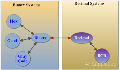
Figure 1: Number of Systems
We can easily convert numbers between decimal and binary systems. If you need to convert a BCD number to another system, such as octal, the best solution is to convert the BCD number to decimal first, then convert it to binary, and finally to octal number.
Decimal ↔ Binary
Converting a decimal number to binary in a digital logic course or general computing involves a systematic method. The process is straightforward but requires attention to detail. Here's a step-by-step guide to converting a decimal number to its binary equivalent:
Method 1: Division-Remainder (Integer Part)
Method 1: Division-Remainder Method (Integer Part)
- Start with the Decimal Number: Identify the decimal number you want to convert. Let's use 52 as an example.
- Divide by 2: Divide the number by 2 (the base of the binary system).
- Record the Remainder: Write down the remainder. This will be either 0 or 1.
- Update the Number: Replace the original number with the quotient (the result of the division).
- Repeat: Continue dividing the new number by 2 and recording the remainder until the quotient becomes 0.
- Read the Binary Number: The binary equivalent is read from the bottom remainder to the top.
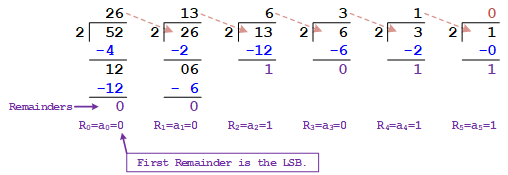
Reading the remainders from bottom to top, the binary equivalent of 52 is (110100)binary.
Method 2: Multiplication Method (Fractional Part)
Method 2: Multiplication Method (Fractional Part)
- Start with the Fractional Part: Separate the fractional part from the integer part of your decimal number. For instance, if you have the number 52.125, your focus is on 0.125.
- Multiply by 2: Multiply the fractional part by 2. Focus on the digit before the decimal point in the result.
- Record the Integer Part of the Result: Write down the integer part of the result (either 0 or 1) as your binary digit.
- Repeat with the New Fractional Part:
- Take the fractional part of the result and multiply it by 2 again.
- Repeat this process until the fractional part becomes 0 or until you reach the desired level of precision.
- Combine the Binary Digits: The binary digits you've recorded in sequence form the binary representation of the original decimal fraction.

So, 0.125 in decimal is (0.001) in binary.
Method 3: Fast Conversion (Using Powers of 2)
Method 3: Fast Conversion (Using Powers of 2)
This method involves finding the largest power of 2 that is less than or equal to the decimal number and subtracting it, then repeating with the remaining value.
- Start with the Highest Power of 2: Create a table with powers of 2 in descending order, starting from the highest power of 2 that is less than or equal to the decimal number.
- Subtract and Mark a 1: Subtract this value from the decimal number, and in the binary representation, mark a 1 in the position corresponding to this power of 2.
- Repeat with the Remaining Value: Use the remainder and find the next highest power of 2. Mark a 1 if it fits or a 0 if it does not.
- Continue Until the Value is 0: Keep going until the remaining value is 0, marking 1s and 0s in their respective positions.
Example: Convert decimal 128.6875 to binary:
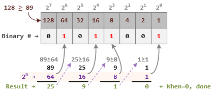
Integer Part: (128)decimal = (101 1001)binary
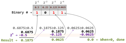
Fractional Part: (0.6875)decimal = (0.1011)binary
So, 128.6875 in decimal is (101 1001.1011) in binary.
Repeating Pattern in Fractional Values:
If a repeating pattern emerges, you can stop the conversion and indicate the repetition using a bar over the repeating digits. Example: Convert 0.3 to binary.
Multiplications:
- 0.3 × 2 = 0.6 (integer part 0)
- 0.6 × 2 = 1.2 (integer part 1)
- 0.2 × 2 = 0.4 (integer part 0)
- 0.4 × 2 = 0.8 (integer part 0)
- 0.8 × 2 = 1.6 (integer part 1)
- 0.6 × 2 = 1.2 (integer part 1)
- ... (pattern repeats 0011)
- Binary equivalent: 0.0100110011... ≈ (0.010011)
Some binary fractions may not terminate or have a repeating pattern. In those cases, you'll need to decide on an appropriate level of precision for your application.
To combine the integer and fractional parts, place a binary point between them. Practice regularly to become proficient in these conversions.
Binary ↔ Decimal
Converting numbers from binary to decimal in a digital logic course involves understanding the base-2 system and how it translates to the base-10 system we commonly use. Here's a step-by-step guide with examples:
Binary Number System:
- Base-2: Binary is a base-2 numeral system. Each digit in a binary number is called a bit and can only be a 0 or a 1.
- Positional Value: Each position in a binary number has a value that is a power of 2, starting from 0 on the right (integer) and -1 on the right (fraction).
Conversion Steps: Binary to Decimal:
- List Down the Powers of 2: Write down the powers of 2 starting from right to left for integer, beginning with 20, and from right to left after the decimal point starting with 2-1.
- Multiply Each Binary Digit with Its Power of 2: For each digit in the binary number, multiply it by the corresponding power of 2.
- Sum the Results: Add all the products together. The sum is the decimal equivalent of the binary number.
Convert (1101.01)2 to decimal.
| 23 | 22 | 21 | 20 | 2-1 | 2-2 | |||
| Position | 3 | 2 | 1 | 0 | -1 | -2 | ||
| (1101.01)2 | = | 1 | 1 | 0 | 1 | . | 0 | 1 |
(1101.01)2 = (1 x 23) + (1 x 22) + (0 x 21) + (1 x 20) + (0 x 2-1) + (1 x 2-2) = (13.25)10
Binary ↔ Octal
- 8 = 23
- Each group of 3 digits in binary represents an Octal digit
Binary to Octal Conversion
- Divide the binary digits into groups of 3 (starting from position 0)
- Convert each group of 3 binary digits to one octal digit.
Example: (10110.01)2 to Octal

Octal to Binary Conversion
- Convert each octal digit to a 3-digit binary number (the octal digits may be treated as decimals for this conversion).
- Combine all the resulting binary groups (of 3 digits each) into a single binary number.
Example: (25)8 to Binary

| Octal | Binary |
|---|---|
| 0 | 000 |
| 1 | 001 |
| 2 | 010 |
| 3 | 011 |
| 4 | 100 |
| 5 | 101 |
| 6 | 110 |
| 7 | 111 |
Binary ↔ Hex
- 16 = 24
- Each group of 4 binary bits represents a Hexadecimal digit
Binary to Hexadecimal
- Divide the binary digits into groups of 4 (starting from position 0)
- Convert each group of 4 binary digits to one hexadecimal symbol.
Example: (11010.01)2 to Hex

Hexadecimal to Binary
- Convert each hexadecimal digit to a 4-digit binary number (the hexadecimal digits may be treated as decimal for this conversion)
- Combine all the resulting binary groups (of 4 digits each) into a single binary number
Example: (15)16 to Binary

| Hex | Binary | Decimal |
| 0 | 0000 | 0 |
| 1 | 0001 | 1 |
| 2 | 0010 | 2 |
| 3 | 0011 | 3 |
| 4 | 0100 | 4 |
| 5 | 0101 | 5 |
| 6 | 0110 | 6 |
| 7 | 0111 | 7 |
| 8 | 1000 | 8 |
| 9 | 1001 | 9 |
| A | 1010 | 10 |
| B | 1011 | 11 |
| C | 1100 | 12 |
| D | 1101 | 13 |
| E | 1110 | 14 |
| F | 1111 | 15 |
Octal ↔ Hex
Convert to Binary as an intermediate step
Example: (26.2)8 to Hex
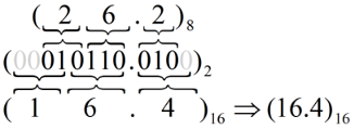
Works both ways (Octal to Hex & Hex to Octal)
Binary ↔ BCD Code
Binary-to-BCD Conversion
To convert binary to BCD, we will first convert the binary number to decimal and then the decimal number to BCD number. Similarly, to convert BCD to binary, we will first convert the BCD to decimal and then convert the decimal to equivalent binary.
Step-by-Step Guide for Binary to BCD Conversion:
- Convert the Binary Number to Decimal
- First, convert the binary number to its decimal equivalent by multiplying each bit by the corresponding power of 2 and summing them up.
- For example, convert binary 10110 1100 to decimal.
Binary 1101100 is 1×26 + 1×25 + 0×24 + 1×23 + 1×22 + 0×21 + 0×20 = 64 + 32 + 0 + 8 + 4 + 0 + 0 = 108 in decimal.
- Convert the Decimal Number to BCD
- Write down each decimal digit as a separate 4-bit binary number (since each decimal digit ranges from 0 to 9, which can be represented by 4 binary digits).
- Separate 108 into 1, 0, and 8.
- Convert to binary:
1 is 0001 in binary.
0 is 0000 in binary.
8 is 1000 in binary. - BCD representation: (0001 0000 1000)BCD.
Binary ↔ Gray Code
Binary-to-Gray Code Conversion
Gray code is a binary numeral system where adjacent numbers differ by only one bit. It is used in error correction, position encoding, and communication systems to minimize errors due to bit changes.
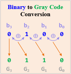
Binary to Gray Code Conversion
The conversion process from binary code to Gray code involves the following steps:
- MSB (most significant bit) or the leftmost bit of the given binary is the same as MSB of the Gray number.
- To get the next bit of Gray code, perform XOR (exclusive OX) MSB with the next bit of binary number (move from left to right). Write the sum and discard the carry.
- Repeat step 2 for all the bits in the sequence till LSB.
Gray to Binary Code Conversion
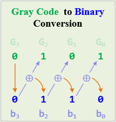
The steps given below are required to be followed to convert a given Gray value into its binary equivalent:
- MSB does not change. So, write the leftmost bit of Gray code as the MSB of binary code.
- Now, perform XOR recently achieved binary digit with the next adjacent Gray code bit. The sum must be written as the next bit of binary equivalent, while the carry must be discarded.
- The above-discussed step must be followed for all the bits present in the sequence.
The 1-bit XOR can be represented as adder logic.
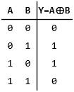
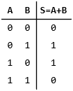
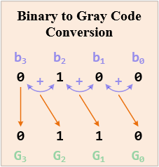
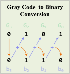
Figure 2: Gray code Conversion using adder
MISC
Ex1: Octal to Decimal
Convert (432.2)8 to decimal.
| 82 | 81 | 80 | 8-1 | |||
| Position | 2 | 1 | 0 | -1 | ||
| (432.2)8 | = | 4 | 3 | 2 | . | 2 |
(432.2)8 = (4 x 82) + (3 x 81) + (2 x 80) + (2 x 8-1) = (282.25)10
Ex2: Hexadecimal to Decimal
Convert (B65F)16 to decimal.
| 163 | 162 | 161 | 160 | ||
| Position | 3 | 2 | 1 | 0 | |
| (B65F)16 | = | B | 6 | 5 | F |
(B65F)16 = (11 x 163) + (6 x 162) + (5 x 161) + (15 x 160) = (46,687)10
Ex3: Base-5 to Decimal
Convert (142.2)5 to decimal.
| 52 | 51 | 50 | 5-1 | |||
| Position | 2 | 1 | 0 | -1 | ||
| (142.2)5 | = | 1 | 4 | 2 | . | 2 |
(142.2)5 = (1 x 52) + (4 x 51) + (2 x 50) + (2 x 5-1) = (47.4)10
Ex4: (315.312510)10 to Octal
Converting Integral Number
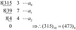
Converting Fractional Number

∴ (315.3125)10 = (437.24)8
Common Powers
Most of the common powers of base-10 and base-2 number systems are shown as follows:
| Power | Preface | Symbol | Value |
| 10-12 | pico | p | 0.000000000001 |
| 10-9 | nano | n | 0.000000001 |
| 10-6 | micro | µ | 0.000001 |
| 10-3 | milli | m | 0.001 |
| 103 | kilo | K | 1,000 |
| 106 | mega | M | 1,000,000 |
| 109 | giga | G | 1,000,000,000 |
| 1012 | tera | T | 1,000,000,000,000 |
| Power | Preface | Symbol | Value |
| 210 | kilo | K | 1,024 |
| 220 | mega | M | 1,048,576 |
| 230 | giga | G | 1,073,741,824 |
| 240 | tera | T | 1,099,511,627,776 |
| 250 | peta | P | |
| 260 | exa | E | |
| 270 | zetta | Z | |
| 280 | yotta | Y |
1.4 Negative Numbers in Binary
It's important to differentiate between unsigned and signed binary numbers to understand how negative numbers are represented in binary.
- Unsigned binary numbers only represent non-negative values ( ≥ 0 ).
An unsigned binary number has no arithmetic sign. Unsigned binary numbers are, therefore, always positive. Typical examples are your age or a memory address which are always positive numbers. An 8-bit unsigned binary integer represents all numbers from 0016 through FF16 (010 through 25510). - Signed binary numbers can represent both positive and negative values using a sign bit.
Signed binary numbers, on the other hand, include both positive and negative numbers. One bit is typically allocated as the signed bit. This sign bit is usually the most significant bit (MSB) — the leftmost bit in the number.- Positive Numbers: In most representations, the number is considered positive if the sign bit is 0.
- Negative Numbers: The number is considered negative if the sign bit is 1.

The techniques used to represent the signed integers are:
- Sign-magnitude approach
- One's complement approach
- Two's complement approach
Sign-Magnitude
Sign-Magnitude
The most significant bit (MSB) is used as the sign bit in the sign-magnitude approach. The rest of the bits represent the magnitude of the number.
- Positive Numbers:
To represent a positive number, you write its binary form and make sure the MSB is 0.
Example: To represent +5 in an 8-bit sign-magnitude form:- Decimal 5 in binary is 101.
- To make it 8 bits, add zeros at the beginning: 00000101.
- The MSB is 0, indicating a positive number, so +5 is 00000101.
- Negative Numbers:
To represent a negative number, you write the binary form of its absolute value and ensure the MSB is 1.
Steps to Represent a Number in Sign-Magnitude:- Convert the absolute value of the number to binary.
- Set the MSB to 0 for positive numbers or to 1 for negative numbers.
- Decimal 5 in binary is 101.
- To make it 8 bits, add zeros at the beginning: 00000101.
- Change the MSB to 1 to indicate a negative number, so -5 is 10000101.
| Decimal Number | Sign-Magnitude Binary (8-bits) |
| +7 | 0000 0111 |
| -7 | 1000 0111 |
| +127 | 0111 1111 |
| -127 | 1111 1111 |
| +0 | 0000 0000 |
| -0 | 1000 0000 |
Key Points:
- Bit Number: The number of bits determines the range of representable values. For example, with 8 bits, you can represent numbers from -127 to +127.
- Zero Representation: Sign-magnitude allows for two representations of zero: +0 (0000 00000) and -0 (1000 0000), which is considered a drawback of this system.
- Arithmetic Operations: Arithmetic operations (addition, subtraction, etc.) using sign-magnitude can be more complex than with other representations like two's complement.
One's Complement
One's Complement
In one's complement, negative numbers are represented by inverting all the bits of their positive counterparts.
- Positive Numbers: Represented normally with the MSB as 0.
- Positive numbers in one's complement are represented just like in regular binary notation.
- Example: The number +5 in an 8-bit binary system is represented as 00000101.
- Negative Numbers: To represent a negative number in one's complement:
- First, write the positive version of the number in binary.
- Then, invert all the bits (change 0s to 1s and 1s to 0s).
Example: To represent -5 in an 8-bit one's complement form:
- Write +5 in binary: 00000101.
- Invert all bits: 11111010.
| Decimal Number | Conversion | One's Complement Binary (8-bits) for Negative Number |
| +7 | = (0000 0111)2 | |
| -7 | = -(0000 0111)2 = (1111 1000)1's | 1111 1000 |
| -34 | = -(0010 0010)2 = (1101 1101)1's | 1101 1101 |
| -60 | = -(0011 1100)2 = (1100 0011)1's | 1100 0011 |
| +0 | = (0000 0000)2 | |
| -0 | = -(0000 0000)2 = (1111 1111)1's | 1111 1111 |
Key Points:
- Zero Representation: One's complement, like sign-magnitude, also allows for two representations of zero: +0 (0000) and -0 (1111).
- One's complement can lead to complications in arithmetic operations due to these two representations of zero.
- Range of Representable Values: With n bits, you can represent numbers from -(2(n-1)-1) to +(2(n-1)-1).
- Arithmetic Operations: Arithmetic operations using one's complement can be simpler than sign-magnitude but still have some complexities.
Two's Complement
Two's Complement
Two's complement is a system for representing negative integers in binary. It simplifies arithmetic operations and avoids the issues of having two representations of zero, which occurs in one's complement.
- Concept: Represents negative numbers by inverting the bits of the corresponding positive number and adding 1.
- Positive Numbers: Represented normally with the MSB as 0.
- Negative Numbers: Invert all bits of the positive number and add 1.
- Steps to Represent a Negative Number:
To represent a negative number in two's complement:- Start with the binary representation of the positive number.
- Invert all bits (change 0s to 1s and 1s to 0s).
- Add 1 to the inverted result.
- Write +5 in binary: 00000101.
- Invert all bits: 11111010.
- Add 1: 11111010 + 1 = 11111011.
- Steps to Represent a Negative Number:
| Decimal Number | Conversion | Two's Complement Binary (8-bits) for Negative Number |
| +7 | = (0000 0111)2 | |
| -7 | = -(0000 0111)2 = (1111 1000)1's = (1111 1001)2's | 1111 1001 |
| -34 | = -(0010 0010)2 = (1101 1101)1's = (1101 1110)2's | 1101 1110 |
| -60 | = -(0011 1100)2 = (1100 0011)1's = (1100 0100)2's | 1100 0100 |
| +0 | = (0000 0000)2 | |
| -0 | = -(0000 0000)2 = (1111 1111)1's = (0000 0000)2's | 0000 0000 |
Faster Method (Shortcut):
- Start from the Right: Scan the binary number from the right (LSB).
- Copy Zeros: Copy all zeros to the 2's complement result.
- Find First 1: Stop copying when you encounter the first 1.
- Invert Remaining Bits: Invert all remaining bits (including the first 1) to get the 2's complement.

Integer Part

Fractional Part
Additional Notes:
- To convert a 2's complement value back to its negative binary form, follow the same steps in reverse.
- Practice with different negative binary numbers to solidify your understanding.
- Visualize the bit inversion and addition process to grasp the concept better.
1.5 Arithmetic Operations on Binary Numbers
Arithmetic operations on binary numbers are fundamental in digital logic courses and computing. The primary operations are addition, subtraction, multiplication, and division. Let's explore each with examples:
Binary Addition
Binary addition follows the same principles as decimal addition but with only two digits (0 and 1).
Rules of Binary Addition:
| A + B | Carry | Sum |
|---|---|---|
| 0 + 0 | 0 | 0 |
| 0 + 1 | 0 | 1 |
| 1 + 0 | 0 | 1 |
| 1 + 1 | 1 | 0 |
| 1 + 1 + 1 | 1 | 1 |
Example:
Add (0001 1010)2 (26 in decimal) and (0000 1100)2 (12 in decimal).

So, (0001 1010)2 + (0000 1100)2 = (0010 0110)2
Binary Subtraction
Using Subtractor
Binary subtraction also works like decimal subtraction, but you may need to borrow from a higher bit.
Rules of Binary Subtraction:
| A - B | Borrow | Subtract |
|---|---|---|
| 0 - 0 | 0 | 0 |
| 0 - 1 | 1 | 1 |
| 1 - 0 | 0 | 1 |
| 1 - 1 | 0 | 0 |
| 1 - 1 - 1 | 1 | 1 |
Example:
Subtract (0000 1100)2 (12 in decimal) from (0001 1010)2 (26 in decimal).

So, (0001 1010)2 - (0000 1100)2 = (0000 1110)2
Using Adder
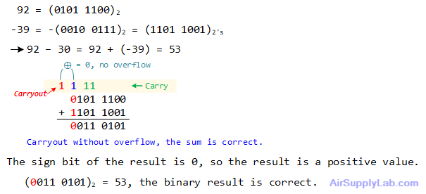
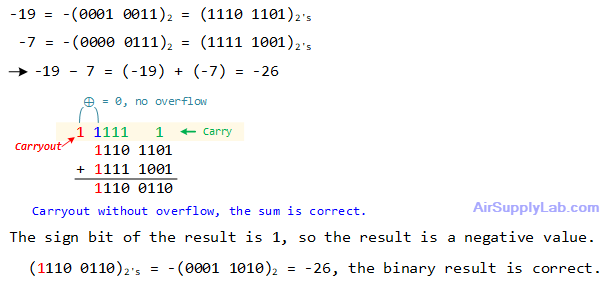
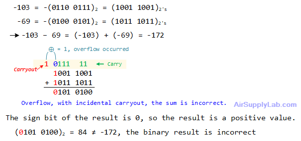
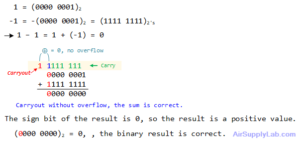
In digital logic and computing, binary subtraction can be performed using an adder circuit by leveraging the concept of Two's Complement. Instead of directly subtracting two binary numbers, we convert the number to be subtracted into its Two's Complement form and then add it to the first number. This approach simplifies the circuitry, as the same adder used for addition can also be used for subtraction.
![]()
Steps for Binary Subtraction Using an Adder:
- Find Two's Complement of the Subtrahend:
- Invert all the bits of the subtrahend (the number you are subtracting).
- Add 1 to the inverted number.
- Add the Minuend and the Two's Complement of the Subtrahend:
- Use a binary adder to add the minuend (the number from which you are subtracting) to the Two's Complement of the subtrahend.
- Interpret the Result:
- If the result has an extra carry-out bit, ignore it.
- The remaining bits give you the subtraction result.
- If overflow occurred, the sum value is not correct.
Example:
Solve the given decimal subtraction problems by first converting them to 8-bit binary addition, finding the binary results, and then reconverting them back to decimal to ensure their correctness.
92 - 39
59 - 75

-19 - 7
-103 - 69
1 - 1
Binary Multiplication
Binary multiplication is simpler than decimal multiplication because each digit is either 0 or 1.
Rules of Binary Multiplication: There are four rules of binary multiplication.
| A × B | Multiplication |
|---|---|
| 0 × 0 | 0 |
| 0 × 1 | 0 |
| 1 × 0 | 0 |
| 1 × 1 | 1 |
Example:
Multiply (0001 1010)2 (26 in decimal) by (0000 1100)2 (12 in decimal).
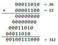
(0001 1010)2 × (0000 1100)2 = (0001 0011 1000)2
Binary Division
The binary division is similar to decimal division but simpler due to its binary nature. It is called the long division procedure.
Example:
Divide (0010 1010)2 (42 in decimal) by (0000 0110)2 (6 in decimal).
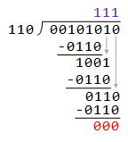
(0010 1010)2 / (0000 0110)2 = (0000 0111)2
1.6 Floating-Point Representation
Floating-point representation in binary is a method to represent real numbers (numbers with fractional parts) that allows for a wide range of values. In digital logic and computer science, floating-point numbers are typically represented using the IEEE 754 standard. This standard includes both single-precision (32-bit) and double-precision (64-bit) formats.
IEEE 754 Standard:
- Commonly used format for floating-point numbers in computers.
- Specifies bit allocation for different precisions (e.g., single-precision, double-precision).
- Three Components:
- Sign Bit: Indicates whether the number is positive (0) or negative (1).
- Exponent: Determines the magnitude or scale of the number.
- Fraction (Significand /Mantissa): Represents the precision or significant digits of the number.
![]()
- floating-point value = (-1)sign × (1 + Fraction) × 2(Exponent - Bias)
- Exponent is biased (excess-K format) to make sorting easier
- bias of 127 for single precision and 1023 for double precision
- Significand in sign-magnitude, the normalized form
- Significand = (1 + Fraction) = 1.b-1 b-2 b-3 … b-23(-52)
- Suppress storage of leading 1
Detailed Steps for Floating-Point Representation:
- Break Down the Number:
- Determine if the number is positive or negative.
- Separate the number into its integer and fractional parts.
- Convert to Binary:
- Convert the integer part to binary.
- Convert the fractional part to binary (usually by multiplying by 2 and taking the integer part repeatedly).
- Normalize the Binary Number:
- Adjust the number so it is in the form of 1.xxxxx... This is called normalizing.
- Keep track of how many places you shift the decimal point, which will be used in the exponent.
- Determine the Sign Bit:
- 0 for positive, 1 for negative.
- Calculate the Exponent:
- The exponent is biased in IEEE 754 format. For 32-bit, the bias is 127.
- Exponent = (Number of shifts to normalize) + Bias
- Convert the exponent to an 8-bit binary number.
- Determine the Mantissa:
- The mantissa is the normalized number, excluding the leading 1 (since it's always 1).
- If necessary, pad the mantissa with zeros to make it 23 bits long.
IEEE 754 Number Range
Floating-point numbers can only represent a specific range of values due to their finite bit representation.
- Overflow: Occurs when a calculation results in a value too large to be accurately represented, leading to loss of precision or even infinite values.
- Underflow: Occurs when a calculation results in a value too small to be distinguished from zero, often leading to zero values or denormalization.

Overflow in IEEE 754
Overflow occurs when a number is too large to be represented in the given floating-point format. This typically results in the number being represented as infinity (positive or negative, depending on the sign).
Ranges Leading to Overflow:
- Single Precision (32-bit): Numbers larger than approximately ± (2-2-23) × 2127 ≅ ± 3.4028235 × 1038 will overflow.
- Double Precision (64-bit): Numbers larger than approximately 1.8 × 10308 will overflow.
When a calculation results in a number exceeding these limits, it is typically represented as positive or negative infinity in IEEE 754 format.
Underflow in IEEE 754
Underflow happens when a number is too small (in absolute value) to be represented in normalized floating-point format. Instead, it may be represented as a denormalized number or, in some cases, as zero.
Ranges Leading to Underflow:
- Single Precision (32-bit):
Numbers (Denormalized) smaller than approximately ± 2-23 × 2-126 = ± 2-149 ≅ ± 1.4012985 × 10-45 (in absolute value) are too small to be represented and lead to underflow.
Numbers (Normalized) smaller than approximately ± 2-126 ≅ ± 1.17549435 × 10-38 (in absolute value) are too small to be represented and lead to underflow. - Double Precision (64-bit): Numbers smaller than approximately 4.9 × 10-324 (in absolute value) are too small to be represented and lead to underflow.
When a calculation results in a number falling below these limits, it may be represented as a denormalized number, allowing for some precision near zero or as zero if it's too small even for a denormalized representation.
Denormalized Numbers:
Denormalized (or subnormal) numbers provide a way to represent numbers that are too small to be normalized but not so small as to be considered zero. They fill the gap around zero and are crucial for gradual underflow, which helps avoid sudden loss of precision in calculations that produce very small results.
IEEE 754 Special Codes
In IEEE 754 floating-point representation, zero and infinity are represented using specific combinations of the sign, exponent, and mantissa bits. These representations allow for the handling of edge cases in mathematical calculations, such as overflow or division by zero, in a standardized way across different computing systems.
- Zero (±0) Representation
- Representation:
- Sign bit: Can be either 0 or 1, representing +0 or -0, respectively
- Exponent: All bits set to 0
- Mantissa: all bits set to 0
- IEEE 754 Format: ± 1.0 × 2-127 ⇒ (S 00000000 00000000000000000000000)IEEE754
- Interpretation: Represents exact zero, either positive or negative.
- Purpose: Essential for distinguishing between zero and very small values within limited precision.
- Representation:
- Infinite Value (±∞) Representation
- Representation:
- Sign bit: 0 for positive infinity (+∞), 1 for negative infinity (-∞).
- Exponent: All bits set to 1
- Mantissa: All bits set to 0
- IEEE 754 Format: ± 1.x × 2128 ⇒ (S 11111111 00000000000000000000000)IEEE754
- Interpretation: Represents positive or negative infinity.
- Purpose: Captures results of operations like division by zero or overflow.
- Representation:
- NaN (Not a Number)
Another special value indicates undefined or unrepresentable results (e.g., the square root of a negative number).- Representation:
- Sign bit: Can be either 0 or 1; the sign of NaN is not meaningful.
- Exponent: All bits set to 1
- Mantissa: Any value (except all bits 0, which represents ∞)
- IEEE 754 Format: ± 1.x × 2128 ⇒ (S 11111111 xxxxxxxxxxxxxxxxxxxxxxx)IEEE754
- Interpretation: Indicates undefined or unrepresentable results (e.g., square root of a negative number, 0/0).
- Purpose: Signals invalid or indeterminate computations.
- Representation:
IEEE 754 Single-Precision Format (32 bits)

Example: Convert the following floating-point values to IEEE 754 Single-Precision Format
10.375
- Number: 10.375 (Positive, so sign bit = 0)
- Binary Conversion:
- Integer part: 10 in binary is (1010)2.
- Fractional part: 0.375 in binary is (0.011)2.
- Combined binary is (1010.011)2.
- Normalize:
- The normalized form is (1.010011)2 × 23
- 3 places shifted, so exponent = 3 + 127 = 130
- The exponent in binary is (1000 0010)2
- Mantissa:
- After the leading 1 (which is dropped), the mantissa is (01001100000000000000000)2 (padded with zeros).
- Complete IEEE754 Format:
- Sign bit: 0
- Exponent: (1000 0010)2
- Mantissa: (01001100000000000000000)2
- Full binary: (0 10000010 01001100000000000000000)IEEE754
- In hexadecimal: 0x41260000
-0.09375
- Sign bit: 1 (Negative)
- Binary Conversion: 0.09375 = (0.00011)2
- Normalize: (0.00011)2 = (1.1)2 × 2-4
- Exponent: -4 + 127 = 123 = (0111 1011)2
- Mantissa: (10000000000000000000000)2
- Binary Representation: (1 01111011 10000000000000000000000)IEEE754
- Hexadecimal: 0xBDC0000
IEEE 754 Double-Precision Format (64 bits)

1.7 Logic Inputs and Outputs
Positive Logic Input
Positive Logic Input in Digital Logic Design
Overview:
In digital logic design, positive logic input refers to a situation where an input signal is considered active or "on" when it is at a high voltage level (logic 1) and inactive or "off" when it is at a low voltage level (logic 0). This concept is crucial for designing circuits interacting with external devices, such as switches, sensors, and microcontrollers.
Definition:
- A positive logic input means that when a device is active, it sends a logic 1 signal to the input of a circuit.
- When the device is inactive, it sends a logic 0 signal.
Example:
Consider a simple switch connected to a microcontroller's input pin.
Circuit Description:
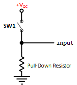
Switch Connection:
- One terminal of the switch is connected to the VCC (power, typically 5V or 3.3V).
- The other terminal is connected to the microcontroller's input pin.
- A pull-down resistor connects the input pin to the ground (GND)
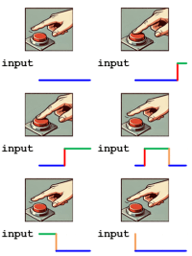
Behavior:
- When the Switch is Pressed (Active State):
- The input pin is connected to Vcc through the closed switch.
- The input pin reads logic 1.
- When the Switch is Not Pressed (Inactive State):
- The input pin is connected to GND through the pull-down resistor.
- The input pin reads (weak) logic 0.
Pull-Down Resistor:
- The pull-down resistor ensures the input pin does not float when the switch is not pressed.
- Without the pull-down resistor, the input pin could be undefined (logic Z), leading to unpredictable behavior.
- The value of the pull-down resistor should be chosen so that it effectively pulls the input to the ground without consuming excessive power. Typical values range from 1kΩ to 10kΩ.
Summary:
A positive logic input circuit uses a pull-down resistor to ensure that an input pin reads a defined low voltage (logic 0) when a connected device, such as a switch, is inactive. When the device is active, the input pin reads a high voltage (logic 1). This setup ensures reliable and predictable behavior in digital circuits.
Example Implementation in a Microcontroller
bool sw1;

sw1 = PORTB->DATA & _BIT2;    // Read SW1 (connect at PB2)
if (sw1 == true) {
    printf("Switch is pressed");
} else {
    printf("Switch is not pressed.")
}
In this example, the input pin connected to the switch is read. When the switch is pressed, the input pin reads HIGH (logic 1); otherwise, it reads LOW (logic 0), demonstrating a positive logic input configuration.
Negative Logic Input
Negative Logic Input in Digital Logic Design
Overview:
Negative logic input refers to a situation where an input signal is considered active or "on" when it is at a low voltage level (logic 0) and inactive or "off" when it is at a high voltage level (logic 1). This concept is often used when detecting a low signal as an active state is more convenient or efficient.
Definition:
- A negative logic input means that when a device is active, it sends a logic 0 signal to the input of a circuit.
- When the device is inactive, it sends a logic 1 signal.
Example:
Consider a simple switch connected to a microcontroller's input pin.
Circuit Description:
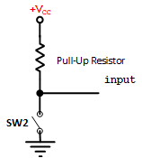
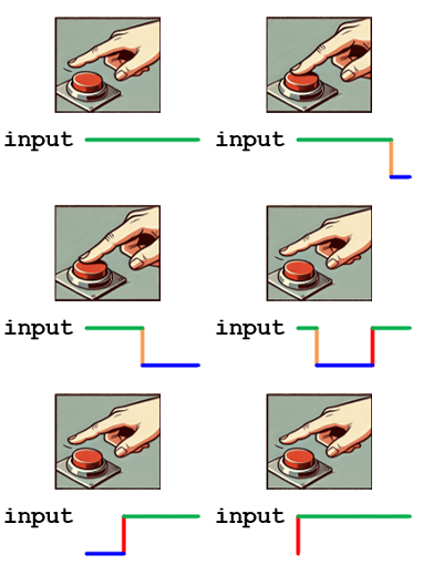
Switch Connection:
- One terminal of the switch is connected to the ground (GND).
- The other terminal of the switch is connected to the input pin.
- The input pin is also connected to Vcc through a pull-up resistor.
Behavior:
- When the Switch is Pressed (Active State):
- the input pin is directly connected to the ground (GND).
- The input pin reads logic 0.
- When the Switch is Not Pressed (Inactive State):
- The circuit is completed through the pull-up resistor to Vcc.
- The input pin reads (weak) logic 1.
Pull-Up Resistor:
- The pull-up resistor ensures the input pin does not float when the switch is not pressed.
- Without the pull-up resistor, the input pin could be undefined (logic Z), leading to unpredictable behavior.
- The value of the pull-up resistor should be chosen so that it effectively pulls the input to Vcc without consuming excessive power. Typical values range from 1kΩ to 10kΩ.
Summary:
A negative logic input circuit uses a pull-up resistor to ensure that an input pin reads a defined high voltage (logic 1) when a connected device, such as a switch, is inactive. When the device is active, the input pin reads a low voltage (logic 0). This setup ensures reliable and predictable behavior in digital circuits where a low signal indicates an active state.
Example Implementation in a Microcontroller:
bool sw2;

sw2 = PORTB->DATA & _BIT4;    // Read SW1 (connect at PB2)
if (sw1 == false) {
    printf("Switch is pressed");
} else {
    printf("Switch is not pressed.")
}
In this example, the input pin connected to the switch is read. When the switch is pressed, the input pin reads LOW (logic 0); otherwise, it reads HIGH (logic 1), demonstrating a negative logic input configuration.
Positive Logic Output
Positive Logic Output in Digital Logic Design
Overview:
In digital logic design, a positive logic output means that an output pin delivers a high voltage level (logic 1) to activate a connected device and a low voltage level (logic 0) to deactivate the device. This concept is widely used in applications where an output signal controls devices like LEDs, relays, and other actuators.
Basic Concept of Positive Logic Output:
- Logic 1 (High): The output signal is at a high voltage level (typically Vcc), activating the connected device.
- Logic 0 (Low): The output signal is at a low voltage level (typically GND), deactivating the connected device.
Example:
LED Connection Example
Circuit Description:
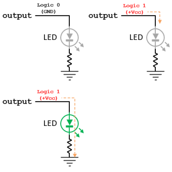
Actions:
- When the Output is Logic 1 (Active State):
- The output pin delivers Vcc.
- Current flows from the output pin through the LED and the current-limiting resistor to the ground.
- The LED lights up, indicating the active state.
- When the Output is Logic 0 (Inactive State):
- The output pin is set to GND.
- No current flows through the LED and resistor.
- The LED remains off, indicating the inactive state.
Current-Limiting Resistor:
- The current-limiting resistor prevents excessive current from flowing through the LED, which could damage it. It also protects the microcontroller's output pin from drawing more current than it can safely handle. Most microcontrollers can typically deliver around 15-20 mA of output current.
- The resistor value is chosen based on the desired current through the LED, typically using Ohm's Law:
$$R = \frac{{{V_{CC}} - {V_{LED}}}}{{{I_{LED}}}}$$
LED Orientation:
Ensure the LED is correctly oriented with the anode (longer leg) connected to the output pin and the cathode (shorter leg) connected to the resistor and ground.
Summary:
A positive logic output circuit controls a connected device by delivering a high voltage level (logic 1) to activate the device and a low voltage level (logic 0) to deactivate it. This configuration is essential for predictable and reliable control of devices like LEDs, where a high signal turns the device on, and a low signal turns it off.
Example Implementation in a Microcontroller:
PORTB->DATA |= _PIN5;          // Set the PB5 output to logic 1, turn the LED on
delayMs(1000);                 // Wait for 1 second
PORTB->DATA &= ~(_PIN5);       // Set the PB5 output to logic 0, turn the LED off
delayMs(1000);                 // Wait for 1 second
In this example, the output pin connected to the LED is toggled between HIGH (logic 1) and LOW (logic 0). The LED lights up when the pin is HIGH, demonstrating a positive logic output configuration. When the pin is LOW, the LED turns off.
Negative Logic Output
Negative Logic Output in Digital Logic Design
Overview:
In digital logic design, a negative logic output means that an output pin delivers a low voltage level (logic 0) to activate a connected device and a high voltage level (logic 1) to deactivate the device. This concept is often used in applications where a low signal is more convenient or efficient to trigger a device.
Basic Concept of Negative Logic Output:
- Logic 0 (Low): The output signal is at a low voltage level (typically GND), activating the connected device.
- Logic 1 (High): The output signal is at a high voltage level (typically Vcc), deactivating the connected device.
Example:
LED Connection Example
Circuit Description:
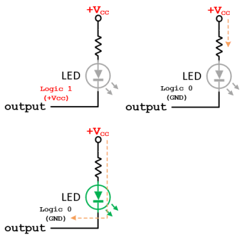
Actions:
- When the Output is Logic 0 (Active State):
- The output pin is set to GND.
- Current flows from Vcc through the current-limiting resistor and the LED to the output pin.
- The LED lights up, indicating the active state.
- When the Output is Logic 1 (Inactive State):
- The output pin is set to Vcc.
- No current flows through the LED and resistor.
- The LED remains off, indicating the inactive state.
Current-Limiting Resistor:
- The current-limiting resistor prevents excessive current from flowing through the LED, which could damage it. It also protects the microcontroller's output pin from sinking more current than it can safely handle. Most microcontrollers can typically sink around 15-30 mA of output current.
- The resistor value is chosen based on the desired current through the LED, typically using Ohm's Law:
$$R = \frac{{{V_{CC}} - {V_{LED}}}}{{{I_{LED}}}}$$
LED Orientation:
Ensure the LED is correctly oriented with the anode (longer leg) connected to the resistor and Vcc and the cathode (shorter leg) connected to the output pin.
Summary:
A negative logic output circuit controls a connected device by delivering a low voltage level (logic 0) to activate the device and a high voltage level (logic 1) to deactivate it. This configuration is essential for predictable and reliable control of devices like LEDs, where a low signal turns the device on, and a high signal turns it off.
Example Implementation in a Microcontroller:
PORTB->DATA &= ~(_PIN7);       // Set the PB5 output to logic 0, turn the LED on
delayMs(1000);                 // Wait for 1 second
PORTB->DATA |= _PIN7;          // Set the PB5 output to logic 1, turn the LED off
delayMs(1000);                 // Wait for 1 second
In this example, the output pin connected to the LED is toggled between LOW (logic 0) and HIGH (logic 1). The LED lights up when the pin is LOW, demonstrating a negative logic output configuration. When the pin is HIGH, the LED turns off.
Questions
Q1: Convert to Binary
Convert the following numbers to binary:
| a) (37)10 | b) (15)10 | c) (187)10 | d) (2014)10 | e) (2016)10 |
| f) (2.75)10 | g) (25.25)10 | h) (243.3125)10 | i) (0.0625)10 | j) (62)8 |
| k) (277)8 | l) (12.6)8 | m) (476.35)8 | n) (96)16 | o) (37FD)16 |
| p) (7FF)16 | q) (1A6)16 | r) (2C0)16 | s) (1F.C)16 | t) (9.F)16 |
| u) (A7.EC)16 |
Q2: Convert to Decimal
Convert the following numbers to decimals:
| a) (1 0110)2 | b) (1 0001)2 | c) (1000 1101)2 | d) (1001 0000 1001)2 | e) (11 1101 0111)2 |
| f) (1011.101)2 | g) (100 1101 1001.1011)2 | h) (30)8 | i) (115)8 | j) (55.4)8 |
| k) (270.54)8 | l) (356)16 | m) (2AF)16 | n) (2C1)16 | o) (10FF)16 |
| p) (1FCFA)16 | q) (DADA.C)16 | r) (F.4)16 | s) (EBA.C)16 | t) (420.32)5 |
Q3: Convert to Hexadecimal
Convert the following numbers to hexadecimal:
| a) (320)10 | b) (6,861)10 | c) (65,535)10 | d) (100)8 |
| e) (62.4)8 | f) (500.25)8 | g) (1000 1101)2 | h) (100_1000_1101_0001_1110)2 |
| i) (1 0000.1)2 | j) (1000 000.0000 111)2 | k) (10 0011 1001.01)2 |
Q4: BCD to Decimal
Convert the following BCD numbers to decimals:
| a) (0001 1000 0100)BCD | b) (0100 1001 0010)BCD | c) (1001 0111 0101 0010)BCD | d) (0111 0111 0111 0101)BCD |
Q5: Convert to Gray Code
Convert the following binary numbers to Gray code:
| a) (1 1011)2 | b) (10 1101)2 | c) (1100 0110)2 |
Q6: Convert Gray to Binary
Convert each of the following Gray codes to a binary number:
| a) (1010)Gray | b) (00010)Gray | c) (110 0001 0001)Gray |
Q7: Binary Add
- (1111)2 + (10101)2
- (10011)2 + (1000)2 + (110011)2
- (1111.101)2 + (111.001)2 + (11.000)2 + (1.111)2
- (1011)2 + (1001)2 + (1111)2 + (1010)2 + (11)2
Q8: Binary Subtract
- (1011)2 - (101)2
- (10001)2 - (11)2
- (10101)2 - (1010)2
- (10000)2 - (1)2
Q9: Binary Multiply
- (101)2 × (11)2
- (1010)2 × (101)2
- (1001)2 × (1001)2
- (111)2 × (111)2
Q10: Binary Divide
- (1111)2 ÷ (100)2
- (1000)2 ÷ (111)2
- (1010)2 ÷ (11)2
- (11101)2 ÷ (110)2
Q11: IEEE 754 Single Precision Format
Represent each of the given base ten numbers in IEEE754 format.
- 5.1
- -14.25
- 6.425