Lab 04: Function Generator and Oscilloscope
Objective
- Measure the output resistance of a function generator and verify it against the datasheet specifications.
- Utilize a digital multimeter (DMM) in conjunction with a function generator to measure AC signals accurately.
- Use an oscilloscope to observe and analyze waveforms generated by a function generator.
- Explore the impact of different load resistances on output voltage from the function generator.
- Understand waveform parameters, including peak voltage, peak-to-peak voltage, RMS voltage, and average voltage for various wave shapes (sine, square, and triangle).
- Practice triggering and scaling functions on an oscilloscope to capture stable waveform displays.
Reading Materials
Equipment
- Function Generator
- Digital Multimeter
- Resistors: 1M, 1K,
Background
- Peak Voltage (Vp): The maximum instantaneous value of a function as measured from the zero-volt level.
- Peak-to-Peak Voltage (Vpp): The full voltage between positive and negative peaks of the waveform; that is, the sum of the magnitude of the positive and negative peaks.
- Root Mean Square Voltage (Vrms): The root-mean-square or effective value of a waveform. The effective voltage would produce the same power in a resistive load as a DC voltage.
- Average Voltage (Vavg): The waveform level is defined by the condition that the area enclosed by the curve above this level is exactly equal to the area enclosed by the curve below this level.
Sine Wave
Sine Wave Voltages — Vp, Vpp, Vavg, Vrms
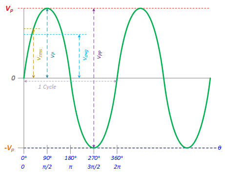
The formula for Sine Wave:
The instantaneous voltage of a sine wave can be expressed as:
- $v(\theta ) = {V_P}\;\sin (\theta )$
- $v(t) = {V_P}{\mkern 1mu} \sin (\omega t) = {V_P}{\mkern 1mu} \sin (2\pi ft)$
Square Wave
Square Wave Voltages — Vp, Vpp, Vavg, Vrms
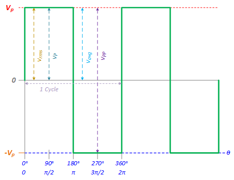
The formula for Square Wave:
The instantaneous voltage of an ideal square wave can be described as:
- $v(\theta ) = \left\{ \matrix{{V_P} & {\rm{for}}\;0 \le \theta < \pi \hfill \cr \hfill \cr - {V_P} & {\rm{for}}\;\pi \le t < 2\pi \hfill \cr} \right.$
- $v(t) = \left\{ \matrix{{V_P} & {\rm{for}}\;0 \le t < {T \over 2} \hfill \cr \hfill \cr - {V_P} & {\rm{for}}\;{T \over 2} \le t < T \hfill \cr} \right.$
Triangle Wave
Triangle Wave Voltages — Vp, Vpp, Vavg, Vrms
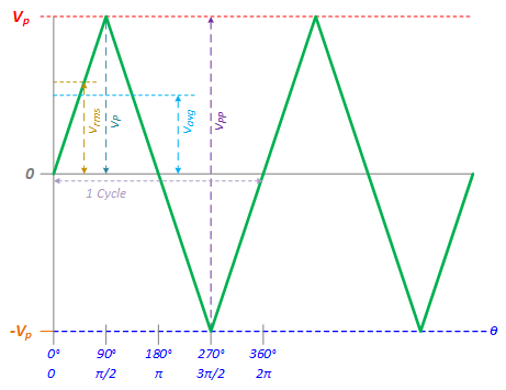
The formula for Square Wave:
The instantaneous voltage of an ideal square wave can be described as:
- $v(t) = \left\{ \matrix{{{4{V_P}} \over T} - {V_P} & {\rm{for}}\;0 \le t < {T \over 2} \hfill \cr \hfill \cr - {{4{V_P}} \over T}t + 3{V_P} & {\rm{for}}\;{T \over 2} \le t < T \hfill \cr} \right.$
| Waveform | Root-Mean-Square Voltage (𝑉rms) | Average Voltage (𝑉avg) |
|---|---|---|
| Sine | ${v_{rms}} = {{{V_P}} \over {\sqrt 2 }} \approx 0.707\;{V_P}$ ${v_{rms}} = {{{V_{PP}}} \over {2\sqrt 2 }} \approx 0.354\;{V_{PP}}$ |
${v_{avg}} = {{2{V_P}} \over \pi } \approx 0.637\;{V_P}$ ${v_{avg}} = {{{V_{PP}}} \over \pi } \approx 0.318\;{V_{PP}}$ |
| Square | ${v_{rms}} = {V_{P}}$ ${v_{rms}} = {{{V_{PP}}} \over 2}$ |
${v_{avg}} = {V_{P}}$ ${v_{avg}} = {{{V_{PP}}} \over 2} = 0.5\;{V_{PP}}$ |
| Triangle | ${v_{rms}} = {{{V_P}} \over {\sqrt 3 }} \approx 0.577\;{V_P}$ ${v_{rms}} = {{{V_{PP}}} \over {2\sqrt 3 }} \approx 0.289\;{V_{PP}}$ |
${v_{avg}} = {{{V_P}} \over 2} = 0.5\;{V_P}$ ${v_{avg}} = {{{V_{PP}}} \over 4} = 0.25\;{V_{PP}}$ |
$${V_{PP}} = 2 \times {V_P}$$
Procedure
Exp #1: Output Resistance of the Function Generator
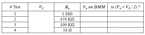
Connect a Digital Multimeter to the Function Generator. In the function generator, set the frequency to 1 kHz and the output voltage to 1.0 Vrms (read on the Multimeter). Then connect a fixed resistor across (i.e. in parallel with) the output of the Function Generator. Change the resistance until the output voltage is down to about one-half of its original value. Record the voltage and resistance values.
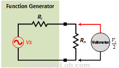
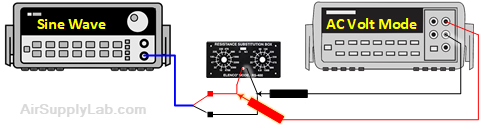
Figure 1: The Output Resistance of the Function Generator Measurement
Question
- Determine the output resistance of the Function Generator and compare it with the specified value found in the datasheet provided in the Reading Materials.
Exp #2: Oscilloscope
Connect the Function Generator's main output to the Channel 1 input of the oscilloscope and a DMM (all in parallel). Connect the Function Generator sync (synchronization) output to the Channel 2 oscilloscope input. On the oscilloscope, set the trigger signal source on channel 2, and the trigger slope to a positive slope.
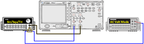 Figure 2: The Connection for Exp #2, #3, #4 and #5
- Set the Function Generator to give a sine wave output at a frequency = 1 KHz. Adjust the amplitude to provide a peak-to-peak voltage of 2 V, as observed on the oscilloscope. Press the Auto-Scale button on the oscilloscope for the initial settings. Then, only the sine wave is displayed on Channel 1.
- Import oscilloscope display to computer: save the screen to the USB flash drive and paste it into your report.
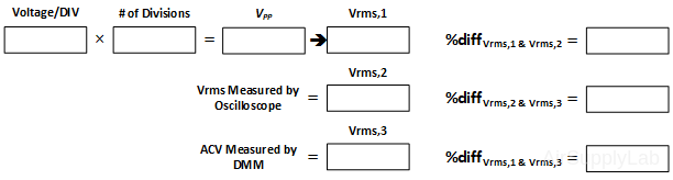
- Compare the peak-to-peak voltage measured by counting divisions and using the voltage/DIV scale to that obtained from the oscilloscope direct voltage measurement.
- Record the RMS voltage as observed on the DMM. Compare that to the RMS voltage as measured by the oscilloscope.
- Compare the RMS voltage with the expected value based on the peak-to-peak voltage.
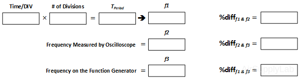
- Measure the period of the waveform by counting divisions and using the time/DIV scale. Find the frequency and compare it to the expected value.
- Obtain the period of the waveform using direct measurement of the oscilloscope. Compare this to the value obtained by counting divisions and using the time/DIV scale.
- Obtain the frequency of the waveform using direct measurement of the oscilloscope. Compare with the value set on the Function Generator.
Function Generator Settings - Frequency: 1KHz, Waveform: Sine Wave, VPP: 2V
- Set the Function Generator to give a square wave output at a frequency = 1 KHz with an amplitude of 2 V peak-to-peak voltage as observed on the oscilloscope. Repeat the above steps a. to g. again.
Function Generator Settings - Frequency: 1KHz, Waveform: Square wave, VPP: 2V - Set the Function Generator to give a triangle wave output at a frequency = 1 KHz with an amplitude of 2 V peak-to-peak voltage as observed on the oscilloscope. Repeat the above steps a. to g. again.
Function Generator Settings - Frequency: 1KHz, Waveform: Triangle Wave, VPP: 2V
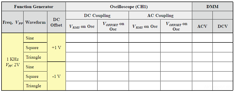
Exp #3: DC Offset
Procedure
- Same connection as Exp#2 in Figure 2.
- Set the DMM to read DC volts. Turn on the DC OFFSET control on the Function Generator and rotate it to give a DC offset of +1 V. Measure the shift in the DC level on the oscilloscope and compare it with the value of DC voltage indicated by the DMM. Set the DMM to read AC volts.
Question
- What is the change in the DMM AC voltage reading as the DC offset is changed from zero to +1 V?
- Repeat the previous procedure with a DC offset of -1 V.
- Change the input coupling switch to AC.
- Now observe what happens.
Exp #4: Trigger Slope
Procedure
- Set the Function Generator back to a SINE WAVE output. Change the Trigger slope to NEGATIVE SLOPE on the oscilloscope and observe what happens. Now change the TRIGGER SLOPE to POSITIVE SLOPE.
Question
- Observe the results.
Exp #5: Sweep Speed
Procedure
- Change the sweep speed control (TlME/DlV) to 0.5 ms/DIV. Measure the period and compare it with the previous result.
- Repeat the previous procedure for sweep speeds (TIME/DIV) of 1.0 ms/DIV, 2.0 ms/DIV, and 0.1 ms/DIV.
- Set sweep speed to 0.1 ms/DIV. Measure the period for the following frequencies and compare with the expected values: 2 KHz, 4 KHz, and 10 KHz.
Questions
- What value of output resistance would the "ideal" Function Generator have? Explain.
- A Function Generator is adjusted to give a no-load (open-circuit) voltage of 1.0 V. When a 1 KΩ load is placed across the output terminals of the Function Generator, the output voltage drops to 0.8 V. Find the output resistance of the Function Generator.
- Voltage Ratio in decibels $(dB) = 20{\log _{10}}\left( {\frac{{{V_1}}}{{{V_2}}}} \right)$
- Express the following ratios in decibels (dB):
- V1 / V2 = 100
- V1 / V2 = 0.1
- Change these dB values to voltage ratios:
- -10 dB
- 3 dB
- Express the following ratios in decibels (dB):
- A Function Generator has a specification that the variation in the output voltage with frequency will remain flat to within ±1 dB over the frequency range of 10 Hz to 100 kHz. Find the corresponding maximum percentage variation in the output voltage over this frequency range.