Lab 10: Mesh and Nodal Analysis
Objective
- Practice wiring several voltage sources on a bread board using one power supply.
- Demonstrate the validity of Mesh and Nodal analysis through experimental measurements.
- Use Loop currents to predict voltages across resistors and Node voltages to determine current through resistors.
Equipments
Background
The mesh analysis determines the mesh or loop currents of the circuit, while the nodal analysis will provide the potential levels of the nodes with respect to some reference. The application of each technique follows a sequence of steps, each of which will result in a set of equations with the desired unknowns. It is then only a matter of solving these equations for the various variables, whether they are current or voltage.
Procedure
Exp #1: Mesh Analysis
Construct the circuit:
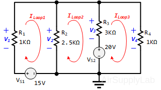
- Use mesh analysis to predict the loop currents (ILoop1, ILoop2, ILoop3) of the circuit. Make sure to label the loop currents and indicate their directions. Include all your calculations and organize your work. Write your calculation results in the table (1a).

- Energize the circuit and measure all the loop currents.
- Use PSpice to simulate the loop currents. Recored the loop currents in the table (1c).
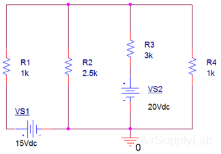

- Compare the following two sets of data:
- Using your loop currents (ILoop1, ILoop2, ILoop3) from (1a) to predict and measure the voltages V2 and V3 (across R2 and R3), and compare them with measured values using a percent difference. How do they compare?
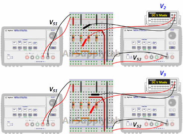
Record your results in the table (1f) ~ (1h).
Exp #2: Nodal Analyses
Construct the circuit:
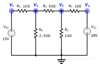
- Use node analysis to predict the node voltages of the circuit. Make sure to label all the nodes. Include all your calculations and organize your work.

- Energize the circuit and measure the node voltages.
- Use PSpice to simulate the node voltages. Recored the node voltages in the table (2c)
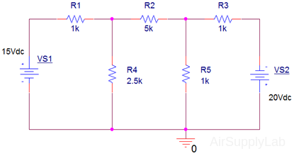

- Compare the following two sets of data:
Organized all your data values into a table! - Using your node voltages (V2, V3) from (2a) to predict and measure the currents I1, I2, and I3 (which current through resistors R1, R2 and R3), and compare them with measured values using a percent difference. How do they compare?
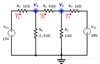

Record your results in the table (2f) ~ (2h).
Exp #3: Bridge Network
Construct the circuit:
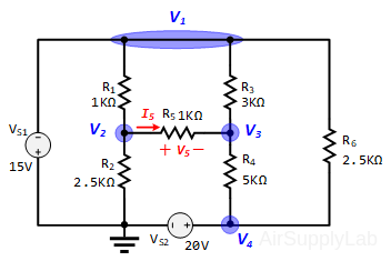
- Use Node analysis to predict the voltage V5 and Mesh analysis to predict the current i5. Write your results in the table (3a).

- Energize the circuit and measure the voltage V5 and current I5.
- Use PSpice to simulate the voltage drop (V5) and the current through (I5) resistor-R5. Use PSpice to simulate the voltage drop (V5) and the current through (I5) resistor-R5.
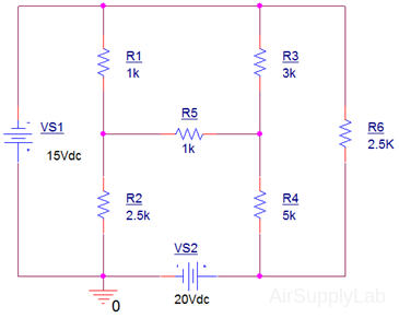

- Compare the predicted (3a) and measured results (3b) using a percent difference? How do they compare?

- Many times one is faced with the question of which method to use in a particular problem. This laboratory activity does not prepare one to make such choices but only shows that the methods work and are solid. From your experience in this activity, summarize in your own words which method you prefer and why for this circuit.
Questions
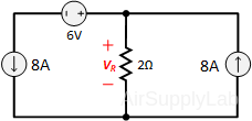
- The voltage (VR) across the 2 Ω resistor in the following circuit?
- 6 V
- 16 V
- -8 V
- 32 V
- None of the above
