1-Wire Communication
The basis of 1-Wire technology is a serial protocol using a single data line plus a ground reference for communication. The 1-Wire protocol uses CMOS/TTL logic and operates at a supply voltage ranging from 2.8V to 6V.
Overview of the 1-Wire BUS
The 1-Wire bus is a simple, low-cost communication protocol primarily designed for connecting multiple devices over a single data line and a ground line. Though the Dallas 1-Wire and MaxDetect (or DHT) 1-Wire protocols use a single data line, they operate differently and are incompatible due to timing, signaling, and data structures. Here’s an overview of each:
General Features of the 1-Wire Bus
- Single Wire Communication: Both protocols use a single data line (plus ground) for communication, making them simple and cost-effective.
- Master-Slave Architecture: In both protocols, a master (typically a microcontroller) initiates communication with one or more slave devices.
- Half-Duplex Communication: The data line is shared for sending and receiving data, meaning devices communicate in only one direction at a time.
Dallas 1-Wire Protocol
Dallas 1-Wire Protocol (Used by Maxim Integrated Devices)
Overview:
The Dallas 1-Wire protocol, developed by Dallas Semiconductor (now Maxim Integrated), is the most well-known 1-Wire protocol. It is widely used in temperature sensing, data logging, and device identification applications. It is especially popular for its simplicity and ability to communicate with multiple devices on the same bus.
Key Characteristics:
- Physical Structure: A single data line plus ground.
- Device Addressing: Each Dallas 1-Wire device has a unique, factory-programmed 64-bit address, which allows multiple devices to coexist on the same bus.
- Parasitic Power: Many Dallas 1-Wire devices can operate in “parasitic power” mode, drawing power from the data line itself, which reduces the need for an additional power line.
- Timing and Protocol: Communication is managed through specific timing sequences (reset, presence detection, read, and write). Data is typically sent as bits in time slots.
- Use Cases: Commonly used for devices such as temperature sensors (e.g., DS18B20), ID chips (e.g., DS2401), EEPROM storage (e.g., DS2431), and secure authentication.
Typical Applications:
- Temperature Monitoring: Often used for industrial and consumer temperature monitoring.
- Device Identification: Allows unique identification of connected devices.
- Data Storage: Small, secure EEPROM devices.
Dallas 1-Wire Protocol
Initialization Procedure
Reset and Presence Pulses Phase
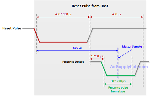
The Dallas 1-Wire initialization procedure is a critical part of establishing communication between the master (typically a microcontroller) and one or more slave devices (such as temperature sensors, memory chips, or ID chips) on the 1-Wire bus. The initialization procedure consists of two main steps: the Reset Pulse and the Presence Pulse. These signals ensure synchronization between the master and slave(s) and confirm that at least one slave device is on the bus and ready for communication.
Step 1: Reset Pulse
The Reset Pulse is generated by the master device to signal the beginning of communication and synchronize all devices on the bus.
Detailed Process of the Reset Pulse:
- Master Pulls the Bus Low:
- The master initiates the reset procedure by pulling the 1-Wire bus line low for a specific duration. This low signal informs any slave device on the bus that a communication session is about to begin.
- The master must hold the bus low for 480 μs or longer (typical values range from 480 μs to 960 μs).
- Master Releases the Bus:
- After holding the bus low, the master releases it, allowing the line to return to a high (idle) state.
- This high period, following the low reset pulse, allows slave devices to detect the reset signal and prepare to respond.
- The idle high period typically lasts for 15 to 60 μs.
Purpose of the Reset Pulse:
- The reset pulse serves as a signal to all connected devices to prepare for communication. All slaves that detect this reset pulse know that the master is requesting a presence check, and they should respond accordingly if they are functional and ready.
Step 2: Presence Pulse
After detecting the reset pulse, each slave device on the 1-Wire bus responds with a Presence Pulse to confirm its presence and readiness for communication.
Detailed Process of the Presence Pulse:
- Slave Detects the Reset Pulse:
- When a slave device detects the reset pulse, it waits for a short period (usually around 15 to 60 μs) after the master releases the bus to confirm that the reset pulse has ended.
- Slave Pulls the Bus Low:
- The slave device then pulls the bus low to signal its presence. This low pulse, known as the presence pulse, informs the master that one or more devices are on the bus and ready to communicate.
- The duration of the presence pulse is typically 60 to 240 μs.
- Slave Releases the Bus:
- After holding the presence pulse, the slave releases the bus, allowing it to return to the idle high state.
- Once the bus returns to high, the master can proceed with the following communication steps: ROM or data commands.
Purpose of the Presence Pulse:
- The presence pulse serves as an acknowledgment from the slave(s) to the master, confirming that at least one device is on the bus and ready for further commands.
- If no slave device pulls the line low after the reset pulse, the master can assume that no devices are connected or responding.
Summary of Timing
Here’s a summary of the timing requirements for the Dallas 1-Wire initialization procedure:
| Step | Signal | Duration |
|---|---|---|
| Reset Pulse | Master pulls low | ≥ 480 μs |
| Master releases | 15 ~ 60 μs | |
| Presence Pulse | Slave pulls low | 60 ~ 240 μs |
| Slave releases | — |
Additional Notes:
- Timing Sensitivity: The Dallas 1-Wire protocol is highly timing-sensitive, so precise timing is crucial. If the timing is incorrect, the devices may not correctly interpret the reset and presence pulses, leading to communication errors.
- Multiple Slaves: The presence pulse is shared on the bus, meaning that if multiple slave devices are present, they all respond with a presence pulse. The master only needs to detect the low signal and does not differentiate between multiple slaves based on the "presence pulse".
Time Slots for Data 1 and 0
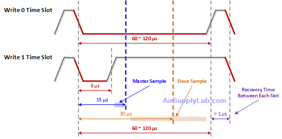
The Dallas 1-Wire protocol transfers data between the master and slave devices using time slots representing binary "0" and "1" bits. Each bit is transmitted within a single time slot, and the interpretation of a "0" or "1" depends on the timing of the low and high states on the 1-Wire bus. The protocol defines precise timing requirements for writing (sending) and reading (sampling) data bits to ensure reliable communication.

Here is a detailed explanation of the time slots for transmitting "0" and "1" bits, including the roles of the master and slave and the sampling timing.
Writing Time Slots (Master to Slave)
Writing Time Slots (Master to Slave)
When the master sends data to the slave, it controls the time slots to indicate either a "0" or "1" bit. Each time slot is approximately 60–120 μs long, with specific timing requirements to differentiate between a "0" and "1".
Writing a "0" Bit
- Master Pulls the Line Low:
- The master begins the time slot by pulling the 1-Wire bus low to indicate the start of a bit.
- Duration: The master holds the bus low for the majority of the time slot, typically around 60 ~ 120 μs.
- Master Releases the Line:
- After holding the bus low, the master releases it, allowing it to return to a high state.
- Timing Requirement: The master must keep the line low for at least 60 μs to ensure the slave interprets it as a "0" bit.
- Slave Reads the Line:
- The slave samples the line during a specific period, typically within the 15 ~ 30 μs window after the start of the time slot.
- Interpretation: If the line is low when the slave samples, the bit is interpreted as a "0".
Writing a "1" Bit
- Master Pulls the Line Low:
- The master pulls the 1-Wire bus low to start the time slot.
- Duration: The master holds the line low briefly, usually 6 ~ 15 μs.
- Master Releases the Line Early:
- After the short low pulse, the master releases the bus, allowing it to return to a high state.
- Timing Requirement: The master should release the line before 15 μs have passed, and the line should remain high for the remainder of the time slot.
- Slave Reads the Line:
- The slave samples the line around 15 ~ 30 μs after the start of the time slot.
- Interpretation: If the line is high when the slave samples, the bit is interpreted as a "1".
Summary of Writing Time Slot Timing
| Bit | Master Low Duration | Master Releases (High) | Slave Sampling Time | Interpretation |
|---|---|---|---|---|
| 0 | ≥ 60 μs | Low for most of the slot | 15–30 μs (line low) | Interpreted as "0" |
| 1 | 6 ~ 15 μs | High for most of the slot | 15–30 μs (line low) | Interpreted as "1" |
Reading Time Slots (Slave to Master)
Reading Time Slots (Slave to Master)
When the master reads data from the slave, the time slots follow a similar structure, with the master initiating each slot and the slave responding with either a "0" or "1" bit. Each time slot is still around 60 ~ 120 μs long.
Reading a "0" Bit
- Master Pulls the Line Low:
- The master starts the time slot by pulling the bus low to indicate that it wants to read a bit.
- Duration: The master briefly holds the line low, typically 6 ~ 15 μs, then releases it to allow the slave to drive it.
- Slave Pulls the Line Low:
- If the slave wants to send a "0" bit, it pulls the line low for most of the time slot, keeping it low until near the end.
- Duration: The slave holds the line low for at least 60 μs.
- Master Samples the Line:
- The master samples the line at around 15 ~ 30 μs after the start of the time slot.
- Interpretation: If the line is low when the master samples, the bit is interpreted as a "0".
Reading a "1" Bit
- Master Pulls the Line Low:
- The master starts the time slot by pulling the bus low to request data from the slave.
- Duration: The master briefly holds the line (around 6 ~ 15 μs) and then releases it, allowing the slave to drive the line.
- Slave Releases the Line:
- If the slave wants to send a "1" bit, it keeps the line high for most of the time slot.
- Duration: The slave does not pull the line low, leaving it high.
- Master Samples the Line:
- The master samples the line around 15 ~ 30 μs into the time slot.
- Interpretation: If the line is high when the master samples it, the bit is interpreted as a "1".
Summary of Reading Time Slot Timing
| Bit | Master Low Duration | Master Releases (High) | Slave Response | Master Sampling Time | Interpretation |
|---|---|---|---|---|---|
| 0 | 6 ~ 15 μs | Slave pulls low | Low for most of the slot | 15–30 μs (line low) | Interpreted as "0" |
| 1 | 6 ~ 15 μs | Slave releases (high) | High for most of the slot | 15–30 μs (line high) | Interpreted as "1" |
Key Points and Timing Summary
- Master Timing:
- Initiates each time slot by pulling the line low.
- Sampling Timing: The master samples the line at 15 ~ 30 μs into each time slot to read bits from the slave.
- Slave Timing:
- Data "0" Bit: Slave holds the line low for most of the time slot if it sends a "0".
- Data "1" Bit: Slave releases the line, allowing it to stay high if it sends a "1".
- Time Slot Length:
- Each time slot is approximately 60 ~ 120 μs in duration.
Summary
In the Dallas 1-Wire protocol, time slots are structured with precise timing to allow for accurate bit transmission:
- Writing "0": Master holds the line low for the entire time slot (≥ 60 μs).
- Writing "1": Master briefly holds the line low (6 ~ 15 μs), then releases it.
- Reading "0": Slave holds the line low for most of the slot.
- Reading "1": Slave releases the line, allowing it to remain high.
The careful timing of low and high pulses within each slot allows the master and slave to distinguish between "0" and "1" bits, ensuring reliable data transmission in the 1-Wire protocol.
MaxDetect (DHT) 1-Wire Protocol
MaxDetect (DHT) 1-Wire Protocol
Overview:
The MaxDetect 1-Wire protocol, used by devices like the DHT11 and DHT22 (RHT03), is a custom 1-wire protocol designed for specific sensors. Unlike the Dallas 1-Wire protocol, it is not a general-purpose bus and is mainly used to communicate with humidity and temperature sensors.
Key Characteristics:
- Data Transmission: A single data line communicates temperature and humidity data in fixed packets from the sensor to the master.
- No Unique Addressing: Unlike Dallas 1-Wire devices, DHT sensors lack unique identifiers and typically support only one device per data line.
- One-Way Communication: Data is typically transmitted in one direction, from the sensor to the master.
- Timing and Protocol: The protocol relies on specific timing requirements to distinguish bits. After a start signal, the sensor responds with a fixed-length data packet (usually 40 bits for DHT sensors) representing temperature and humidity.
- Power Requirement: A dedicated power line is required, as DHT sensors do not support parasitic power.
Typical Applications:
- Environmental Monitoring: Primarily used for temperature and humidity sensing in home automation, HVAC systems, and weather stations.
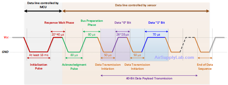
MaxDetect (DHT) 1-Wire Protocol
- Initialization Phase:
The host (master) initiates communication by pulling the bus low for at least 18 ms, signaling the start of the data exchange process. This low signal indicates to the sensor that the host is ready to start communication. - Response Wait Phase:
After the initialization pulse, the host pulls the bus high and waits for the sensor to respond. During this phase, the sensor recognizes the start signal, prepares for communication and gets ready to acknowledge. - Acknowledgment Pulse:
The slave device (sensor) pulls the line low, confirming it is ready to send data. This pulse ensures synchronization between the master and slave. - Bus Preparation Phase:
The bus is held high to prepare for the data output from the sensor. This phase ensures the bus is stable and ready for data transmission. - Data Transmission Initiation:
After the acknowledgment and preparation phases, the sensor sends data to the host. The data typically includes humidity, temperature, and a checksum for error detection. Specific timing patterns represent each bit of data to distinguish between a "0" and a "1" bit.
- Data "0" Bit: If the pulse width is around 26~28 μs, it represents a data "0" bit.
- Data "1" bit: If the pulse width is around 70 μs, it represents a data "1" bit.
- End of Data Sequence:
After transmitting the entire data sequence (typically 40 bits: 16 bits for humidity, 16 bits for temperature, and 8 bits for checksum), there is a final pulse or transition that indicates the end of the data transmission. The sensor releases the bus at this point, allowing it to return to a high state.
Comparison of Dallas and MaxDetect 1-Wire Protocols
| Feature | Dallas 1-Wire Protocol | MaxDetect (DHT) 1-Wire Protocol |
|---|---|---|
| Devices Supported | Temperature sensors, ID chips, EEPROM, secure ICs | Primarily temperature and humidity sensors |
| Addressing | Unique 64-bit address for each device | No unique address, typically single sensor per line |
| Communication Direction | Bi-directional (half-duplex) | Unidirectional (sensor to master only) |
| Parasitic Power Support | Yes | No |
| Data Format | Custom data sequences (typically binary) | Fixed 40-bit data (humidity + temperature + checksum) |
| Applications | Multipurpose, data logging, authentication | Environmental monitoring |
Key Takeaways
- Compatibility: Dallas 1-Wire devices and MaxDetect (DHT) sensors are incompatible due to protocol design, timing, and data structure differences.
- Applications: Dallas 1-Wire is versatile and used for identification, sensing, and data storage, while MaxDetect 1-Wire is specific to certain types of sensors.
- Device Diversity: Dallas 1-Wire supports a wider range of devices with unique addresses, allowing multiple devices on one bus, while MaxDetect 1-Wire typically supports only one sensor per data line.

