Character LCD Module (HD44780-Based)
LCDs (Liquid Crystal Displays) are passive or active-matrix displays that can demonstrate information as text or in a dot matrix pattern. This type of technology is generally less expensive than VFD or OLED display technology. There are two major types of LCD Modules: standard character and graphic LCD module displays. We can display text and numeric data using a character LCD module and images using a graphic LCD module. The character LCD modules are ideal for displaying characters such as text and numbers. They consist of little rectangles where each character is displayed. Each rectangle is an 8X5 grid of pixels. The graphical LCD has one big grid of pixels (i.e. 128X64) and usually, it is used for displaying images. Graphical LCDs tend to be larger, more expensive, difficult to use, and need many more pins.
A character LCD module provides an excellent means for your embedded system to display measurements, status, and conditions with ASCII character strings. The Hitachi HD44780 controller has become an industry standard for the monochrome character LCD module. Character LCD modules are in various sizes, which are measured by the number of rows and columns of characters they can display, such as 16x2, 20x2, and 20x4 formats. Most LCD modules include a backlight and in some of them, you can choose the backlight color. There are various colors like white text on a blue background or black text on the green or black text on grey.
Pinout
Character LCDs use a 16 contact interface, commonly using pins or card edge connections on 0.1 inch (2.54 mm) centers. Those without backlights may have only 14 pins, omitting the two pins powering the light. The figure below shows the LCD module and the pinout.
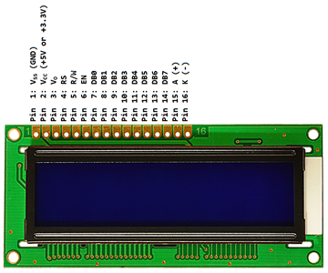
| Pin # | Symbol | Function |
| 1 | VSS | Ground |
| 2 | VCC | +5V to +3.3V |
| 3 | VO | Contrast Adjustment (10KΩ Potentiometer) |
| 4 | RS | Register Select. RS=0: Command, RS=1: Data (*1) |
| 5 | R/W | Read/Write. R/W=0: Write, R/W=1: Read (*2) |
| 6 | EN | Enable (Clock). Falling edge triggered |
| 7 | DB0 | Bit 0 (Not used in 4-bit operation) |
| 8 | DB1 | Bit 1 (Not used in 4-bit operation) |
| 9 | DB2 | Bit 2 (Not used in 4-bit operation) |
| 10 | DB3 | Bit 3 (Not used in 4-bit operation) |
| 11 | DB4 | Bit 4 |
| 12 | DB5 | Bit 5 |
| 13 | DB6 | Bit 6 |
| 14 | DB7 | Bit 7 |
| 15 | A | Backlight Anode (+) (If applicable) |
| 16 | K | Backlight Cathode (-) (If applicable) |
(*1) The control pin RS determines if the data transfer between the LCD module and an external microcontroller is actual character data or command/status.
| RS | R/W | Operation |
| 0 | 0 | Instruction Register writes as an internal operation (display clear, etc.) |
| 0 | 1 | Read busy flag (DB7) and address counter (DB0 to DB6) |
| 1 | 0 | Data Register (DR) write as an internal operation (DR to DDRAM or CGRAM) |
| 1 | 1 | Data Register (DR) read as an internet operation (DDRAM or CGRAM to DR) |
(*2) The R/W pin is optional due to the fact that most of the time you will only want to write to it and not read. Therefore, in general use, this pin will be permanently connected directly to the ground.
4-bit or 8-bit Mode
The character LCD module can work on 4-bit or 8-bit mode.
- 4-bit Mode
- Uses 4 I/O port pins for data and two or three additional I/O pins for control.
- Requires two 4-bit transfers for each command and data that is sent to the display. Each 8-bit value is divided into two 4-bit nibbles. High nibble is sent first following by the lower nibble.
- 8-Bit Mode
- Uses 8 I/O port pins for data and two or three additional I/O pins for control.
- Requires only one 8-bit transfer for each command and data that is sent to the display.
The major difference in 4-bit and 8-bit mode lies in data pins used and LCD initializing commands. In 4-bit mode, only four data pins are used. Character 8-bit ASCII value is divided into two 4-bit nibbles. High nibble is sent first following by the lower nibble. In contrast in 8-bit communication, an 8-bit ASCII value of a character is sent at a single time period and displayed on the LCD. Thus the 4-bit mode generates latency. Although 4-bit mode generates latency it, on the other hand, saves 4 GPIO pins. Which can be utilized elsewhere.
If I/O is limited, a 4-bit mode might be the way to go. If I/O is plentiful, but time is important, the 8-bit mode may be the way to go.
4-bit data transfers also require a bit more code as the lower nibble will need to be shifted into the upper nibble with each command and data transfer.
Model Selection
Selecting 4-bit or 8-bit mode requires a careful selection of commands. There are two primary considerations. First, with D3-D0 unconnected, these lines will always appear low (0b0000) to the HD44780 when it is in 8-bit mode. Second, the LCD may initially be in one of three states:
- (State1) 8-bit mode
- (State2) 4-bit mode, waiting for the first set of 4 bits
- (State3) 4-bit mode, waiting for the second set of 4 bits
State3 may occur, for example, if a prior control was aborted after sending only the first 4 bits of command while the LCD was in 4-bit mode.
The following algorithm ensures that the LCD is in the desired mode:
- Set D7-D4 to 0b0011 and toggle the enable bit.
- If in State1, the LCD will see the command as 0b0011_0000, and thus remain in 8-bit mode (State1).
- If in State2, the LCD will simply latch the value 0b0011 into bits 7-4 and then move to State3.
- If in State3, the LCD will latch the value 0b0011 into bits 3-0, and then execute a random command based on the (unknown to us) values in bits 7-4, after which it will either be in State1 (if the unknown bits happened to be 0b0011) or State2 (if the unknown bits were anything else).
- Repeat the above, setting D7-D4 to 0b0011 and toggling the enable bit again.
- If in State1, the LCD will remain in 8-bit mode (State1) just as above.
- If in State2, it will latch the value into bits 7-4 and move to State3, just as above.
- If in State3, the LCD will latch the value into bits 3-0 just as above and execute a command. However, the command will no longer be random but will be the 0b0011 that was latched from State2 in the previous iteration. Thus, the LCD will switch to the 8-bit mode and change to State1.
- The LCD is now in either State1 or State 3. Repeat the previous step one more time.
- If in State1, the LCD will remain in 8-bit mode (and thus State1).
- The LCD can no longer be in State2 at this point.
- If in State3, the LCD will latch the value into bits 3-0 and execute a command, which will be the 0b0011 that was latched from State2 in the previous iteration, thus switching the LCD to the 8-bit mode and State1.
- Now that the LCD is definitely in 8-bit mode, it can be switched to 4-bit mode if desired. To do so, set D7-D4 to 0b0010 and toggle the enable bit. This will leave the LCD in 4-bit mode, configured for a single line and 5x8 fonts.
- Issue any desired additional Function Set commands to specify the number of lines and the font to use, being sure to use the appropriate value for bit 4 so as to remain in the desired mode (0 for 4-bit and 1 for 8-bit).
Once in 4-bit mode, character and control data are transferred as pairs of 4-bit "nibbles" on the upper data pins, D7-D4. The four most significant bits (7-4) must be written first, followed by the four least significant bits (3-0).
Instruction Set (HD44780)