Infrared Receiver Module for Remote Control Systems
An infrared receiver, or IR receiver, is hardware that sends information from an infrared remote controller to another device by receiving and decoding infrared signals. If an embedded system just needs an easy way to remotely trigger some action, using an IR (Infrared) remote is a great way to have wireless control of the embedded project.
Types of Infrared Receivers
The terms of infrared refer to the wavelength range between 700 nm and 1 mm. This range of wavelengths corresponds to a frequency range of approximately 430 THz down to 300 GHz. But, the most common types of the infrared LED that are used in the IR remote controls are 850 nm and 940 nm, both are not visible light.
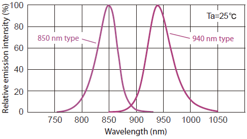
Figure: 850-nm V.S. 940-nm Peak Wavelength Infrared LED Emission Spectrum
There are many different manufacturers of infrared receivers, and different packages have different pin outs:

Carrier Frequency
Infrared remote controls do not output continuous infrared light. The infrared LED output is "chopped" via control circuitry into pulses of a given frequency, that is called "carrier Frequency". The following lists are the carrier frequencies that are commonly used in consumer electronics. The most common one is 38 KHz though.:
- 40 Hz
- 30 KHz
- 33 KHz
- 36 KHz
- 36.7 KHz
- 38 KHz (37.9 KHz)
- 40 KHz
- 56 KHz
Infrared receivers have a demodulator inside that looks for modulated infrared at a specific carrier frequency. Infrared receivers are digital out, either they detect carrier frequency infrared signal and output logic 0 (0 Voltage) or they do not detect any and output logic 1 (5 Voltage).
In the above figure, a modulated signal driving the infrared LED of the transmitter on the left side. The detected signal is coming out of the receiver at the other side.
Modulation
When an infrared LED is on for a brief period of time that is called as a "Mark", and the period of time when it is off that is called as a "Space". A complete sequence of Marks and Spaces is referred to as a "frame" of data. The signal usually starts with a very long mark and space. This header information helps identify the protocol.
The IR Encoder
The actual data to be sent from the IR controller is encoded. The method of encoding used determines how to represent the '1's and '0's in terms of the marks and spaces. The following three methods of encoding are typically used in IR remote control systems.
Pulse Distance Encoding
Pulse Length Encoding
Manchester Encoding
The IR Receivers
The IR receiver in the kit is soldered on an IR Receiver Electronic Brick board as follows:
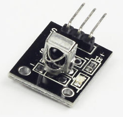
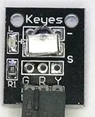
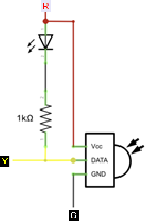
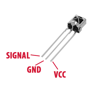
The IR Receiver Electronic Brick Board already has an internal 1K ohm pull-up resistor and connected with a LED in serial between the VCC and DATA pins. It has 3 pins on the little circuit board: G (Ground), V (Voltage), S (Signal). These pins on some of the boards may be marked as G-R-Y, which uses typical color code: G (Ground = Black), R (Voltage = Red), and Y (Signal = Yellow)
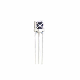
Infrared IR 1838 Remote Control Sensor Module
The AX-1838HS is miniaturized infrared receivers for remote control and other applications requiring improved ambient light rejection.
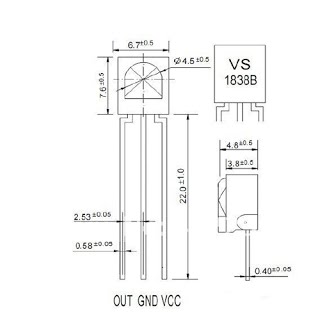
Features:
- Carrier frequency: 38 KHz
- IR wavelength: 940 nm
- The range of supply voltage is +2.1V to 6.5V
- TTL and COMS compatiablity
- 8 ms data pause time codes are acceptable
Type of IR Remote Controllers
There are many different IR remote controllers. The most controllers are typical TV and Player Remotes. Some controllers have directional buttons that would be good for controlling a robot etc. All of these may have different encoding methods and number of physical buttons, and different codes received when a button is pressed.
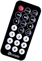
Figure: The IR Remote Controller in the Kit