State Machines in C
If a system's functionality depends on the order in which input events occur, or on input events that occur at different times (states), then these models are called "Time-Ordered Behavior". For example:
- An electronic lock may require a user to press and release button 5, then 3, then 2 to unlock a door
- A fan has only one button. When a user first presses the button to turn on the fan at 25% speed. If the user presses the button continuously, the fan speed will be changed to 50%, 75%, and then 100%. When the fan speed reaches 100% and the user presses the button again, the system will turn off the fan.
State machines are perhaps the most effective method for capturing Time-Ordered Behavior for embedded systems. A state machine has several components:
- Set of inputs and outputs
- Set of states with actions
- Set of transitions with conditions
- and an initial state
The following tools are used to describe the time-ordered behaviors:
- State Diagram:
A drawing of a state machine, also called a State Transition Graph (STG). It is a popular way of representing state machines.
A state diagram includes the following components:
- State: stores information about the past and reflects changes from the system's start to the current state.
- Current State: determined by past states of the system.
- Transition: indicates a change from one state to another. Transitions are invoked by Events.
- Event: the inputs to a state machine.
- Action: also called an output. It is a description of an activity that is to be performed as a result of input and a change of state. An event can be depicted either in the transition or within the state.
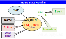
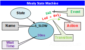
Figure 1: State Diagrams - State Transition Table:
A state transition table (or state table) describes a state machine in a tabular format.
Table 1: State Transition Table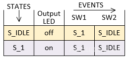
This simple model exemplifies an LED controller that embodies two states: LED off (S_IDLE) and LED on (S_1), and two inputs: SW1 and SW2. If the LED is in the S_IDLE state, and an input SW1 is presented, the state machine progresses to the S_1 state. If an input of SW1 is presented to the machine in the S_1 state, the machine stays in the S_1 state.
There are two models for incorporating actions into state machines:
- Moore
A Moore machine performs actions when entering a state. Each state may have its own entry action. - Mealy
A Mealy machine performs actions on transitions. Each transition in a state machine may invoke a unique action.
Moore and Mealy state machines have their own advantages and disadvantages. But one of the great advantages of both is that they are not mutually exclusive, and these two models can be used together in the system.
Moore State Machine
The interior of the Moore state machine consists of three blocks:
- Next state block: a function of the current state and inputs to decide the next state.
- State Register: to store the current state from the next state.
- Output: depends on the current state.
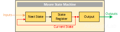
Figure 2: Moore State Machine Architecture
Moore state machine has the following characteristics:
- Output value or action depends on current state: output = F(CurrentState);
- Significance is the state
- Input: when to change state
- Output: what to do while in that state
State Diagram for Moore State Machine
The state diagram of a Moore state machine is shown below:
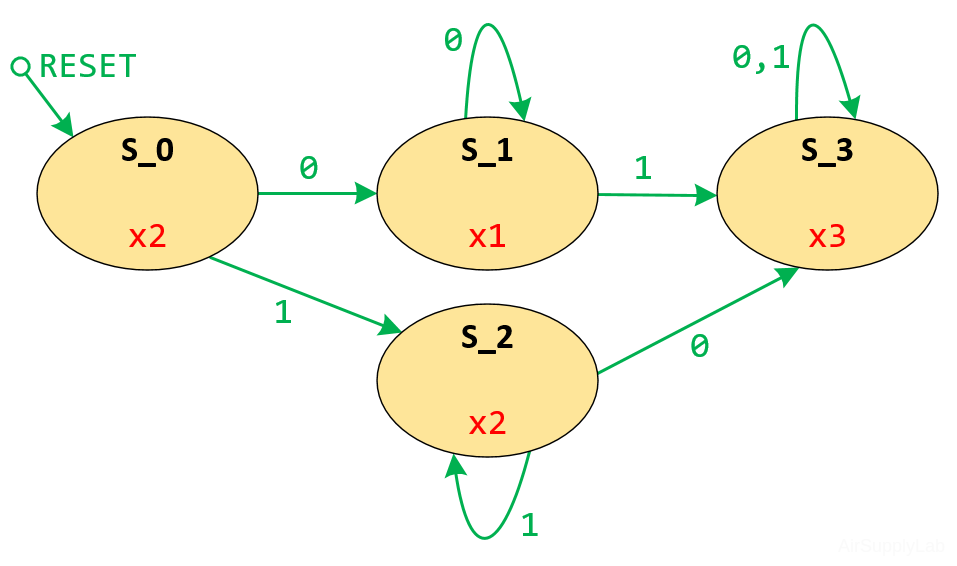
Figure 3: A Moore State Machine
State Transition Table for Moore State Machine
The state transition table of the above Moore state machine is shown below:
Table 2: State Transition Table for Moore State Machine
| State | Output | Next State | |
| Input | |||
| 0 | 1 | ||
| → S_0 | x2 | S_1 | S_2 |
| S_1 | x1 | S_1 | S_3 |
| S_2 | x2 | S_3 | S_2 |
| S_3 | x3 | S_3 | S_3 |
Mealy State Machine
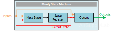
Figure 4: Mealy State Machine Architecture
The output of the Mealy State Machine is the function of the present state as well as the input.
- Output value depends on inputs and current state: output = F(Inputs, CurrentState);
- Significance is the state transition
- Input: when to change state
- Output: how to change state
State Diagram for Mealy State Machine
The state diagram of a Mealy state machine is shown below:
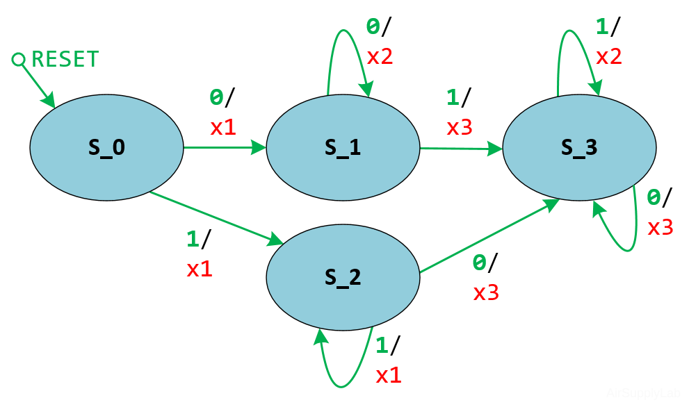
Figure 5: A Mealy State Machine
State Transition Table for Moore State Machine
The state transition table of the above Mealy state machine is shown below:
Table 3: State Transition Table for Mealy State Machine
| State | Next State / Output | |
| Input | ||
| 0 | 1 | |
| → S_0 | S_1 / x1 | S_2 / x1 |
| S_1 | S_1 / x2 | S_3 / x3 |
| S_2 | S_3 / x3 | S_2 / x1 |
| S_3 | S_3 / x3 | S_3 / x2 |
What are the differences between Moore and Mealy state machines? The following table shows the differences between a Moore machine to a Mealy machine:
| Moore State Machine | Mealy Sate Machine |
| Outputs depend on the current state only outputs = F(currentState); nextState = F(inputs, currentState); |
Outputs depend on the current state and the inputs outputs = F(inputs, currentState); nextState = F(inputs, currentState); |
| Generally, it has more states than Mealy | Generally, it has fewer states than Moore |
| The output does not react immediately to an input change (one clock cycle later) | Outputs have an immediate reaction to inputs |
| Output is placed on the states | Output is placed on transitions |
| Easy to design | It is difficult to design |
Implement State Machine in C
The state machine for a stoplight controller is shown in Figure 5.
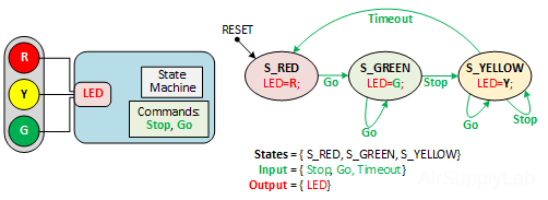
Figure 5: Stoplight Controller
A state diagram can be implemented in three main ways: Nested Switch, the State Pattern, and State Tables.
Nested Switch
Nested Switch is a simple way to implement a state machine in C. It keeps all the logic in one place, but the code can be hard to read when there are many states and transitions. It is possibly more secure and easier to validate than the other approaches.
State Pattern
The State pattern implementation can spread the logic across several classes, potentially making it difficult to understand as a whole. On the other hand, the small classes are easy to understand separately. The design is particularly fragile if you change the behavior by adding or removing transitions, since they're methods in the hierarchy, which could require many code changes. If you live by the design principle of small interfaces, you'll see that this pattern doesn't really do so well. However, if the state machine is stable, then such changes won't be needed.
State Table
The state tables approach requires writing an interpreter for the content (which might be easier if you have a reflection in the language you're using), which could be a lot of work upfront. As Fowler points out, if your table is separate from your code, you can modify your software's behavior without recompiling. This has some security implications; however, the software is behaving based on the contents of an external file.
State machines are a very useful programming model, especially when a system needs to act based on its history (state) and the environment (events). Implementing code using a state machine is very difficult to maintain because the system reacts differently depending on the state and event. Therefore, good documentation is very important.
State Machines vs. Flowcharts
Maybe you will confuse state machines with flowcharts. The most important difference between state machines and flowcharts is that state machines perform the next actions (state) only in response to explicit events; they are event-driven. In contrast, flowcharts do not need to be triggered by events; they are used to describe the progression of a task from start to finish, step by step.
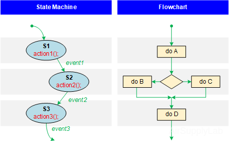
Figure 6: State Machine vs Flowchart
The distinction between state machines and flowcharts is especially important when analyzing system behavior. These two concepts represent diametrically opposed programming paradigms: state machines are event-driven, and flowcharts are transformational.
When you design a state machine, you have to constantly think about available events (inputs). In contrast, events are not the primary concern in flowcharts; procedures are.