PSoC5LP Lab 09: I2C RTC Module
Objective
- Learn how to interface a Real‑Time Clock (RTC) module — such as the DS1307 or DS3231 — with the PSoC5LP MCU using the I²C protocol.
- Set up and configure the I2C Master component in PSoC Creator.
- Retrieve and display real-time data (time and date) from the RTC on a character LCD, enabling accurate timekeeping across power cycles.
- Understand RTC features like battery backup, low power consumption, and alarm/interrupt capability.
Overview
A Real-Time Clock (RTC) module in an embedded system is a dedicated hardware component that accurately tracks time, often across various power cycles. It provides precise timekeeping regarding seconds, minutes, hours, days, months, and years. RTCs are crucial for applications requiring accurate time management, such as data logging, scheduling tasks, alarms, and managing timestamps in file systems.
Key Features and Functions of RTC Modules
- Time and Date Tracking: An RTC maintains accurate time and date information. It can manage leap years, handle month-end adjustments, and keep track of hours, minutes, seconds, day of the week, and year.
- Battery Backup: RTCs typically operate with a low-power backup battery. This feature allows them to continue counting time even when the main power supply is off, ensuring uninterrupted time tracking.
- Low Power Consumption: Most RTC modules consume minimal power, making them ideal for battery-powered devices that require continuous timekeeping, such as wearable devices, portable equipment, and IoT nodes.
- Programmable Alarms and Interrupts: Many RTCs include alarm and interrupt features. Programmable alarms can trigger at specified times or intervals, which is useful for scheduling tasks in low-power modes or waking up the system from sleep.
- I2C or SPI Interface: RTCs commonly use I2C or SPI communication protocols to interface with microcontrollers, allowing simple, reliable integration into embedded systems.
- Automatic Calibration: Some advanced RTCs have self-calibration mechanisms to maintain high accuracy. This feature can correct for drift caused by temperature variations or oscillator aging.
- Applications: RTC modules are essential in applications where maintaining accurate time is critical, including:
- Data logging (e.g., environmental monitoring)
- Scheduled tasks and automation
- Timestamping in file systems
- Alarm systems and reminders
- Low-power devices where periodic wake-ups are necessary
Popular RTC Modules
- DS1307: A widely-used I2C-based RTC with battery backup and basic date/time tracking, suitable for simple applications.
- DS3231: Known for high accuracy, this I2C RTC has an integrated temperature-compensated crystal oscillator (TCXO) and features alarms, making it ideal for precision applications.
- PCF8563: This low-power RTC also uses I2C and is known for its power efficiency, making it popular in portable devices.
In summary, RTC modules in embedded systems enable precise and reliable timekeeping across power cycles, essential for any application requiring accurate time information or scheduled operations. Their low-power design and integration flexibility make them a core component in modern embedded and IoT systems.
In this lab, you will interface a microcontroller with the DS3231 RTC module using I2C to display the current date and time on an LCD, and allow the host PC to update the clock via UART commands. You will learn how to handle I2C register decoding, binary‑coded decimal (BCD) conversion, UART parsing, interrupt-driven design, and state machines — all essential skills for real-time embedded systems.
Required Reading Materials
- Lesson KB 01: Create a PSoC Project using PSoC Creator
- Datasheets:
- PSoC Creator Components
Required Components
The following components are required for this lab.
 |
DS3231 (or DS1307) RTC module | x 1 |
| Character LCD Module | x 1 |
Circuit / Schematic
- Connection for Character LCD Module
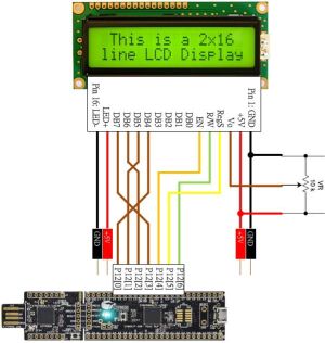
- Connection for DS3231 RTC module

Procedure
Creating a New Project
- Launch PSoC Creator.
- Got to File ➤ Open Project ➤ Project/Workspace.
- Open the PSoC5LP workspace in the EE4450 folder.
- After PSoC Creator opens the workspace, right-click on Workspace 'PSoC5LP' in the Workspace Explorer and select Add ➤ New Project….
- Select the correct PSoC5LP device model number, use the "Empty schematic" template, and enter the project name 09_I2C_RTC.
Adding PSoC Creator Components
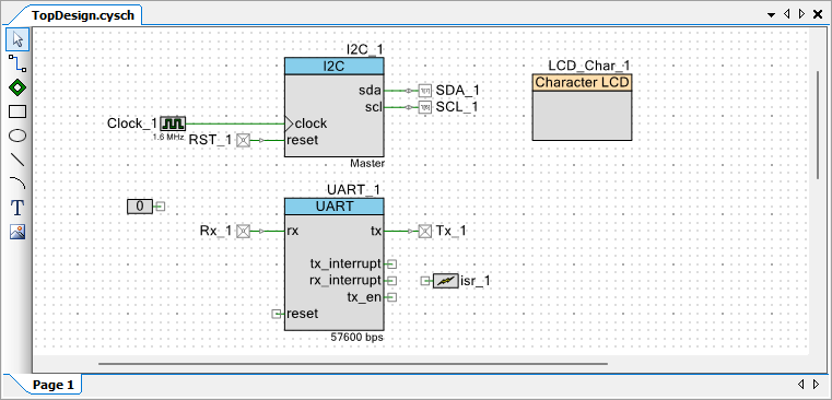
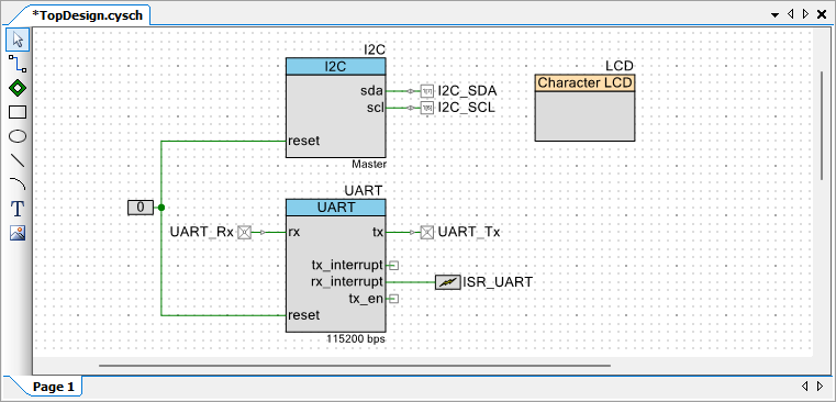
Open the "TopDesign.cysch" Schematic File, add the following components:
- Add a UART:
- In the Communication category.
- Drag and drop a
 UART onto the schematic.
- Add an I2C Master component:
- Still under the Communications category, open the I2C catalog.
- Drag and drop the I2C Master (UDB) onto the schematic.
- Add an Interrupt:
- In the System category.
- Drag and drop an Interrupt onto the schematic.
- Add a Character LCD component:
- In the Display catalog.
- Drag and drop the
 Character LCD onto the schematic.
- Add a Logic Low '0' signal:
- In the Digital ➤ Logic category.
- Drag and drop a Logic Low '0' onto the schematic.
After completing these steps, the schematic will include all necessary components — UART, I2C Master, Interrupt, Character LCD, and Logic Low '0' — ready for configuration and connection in the next stage.
Configure the Components
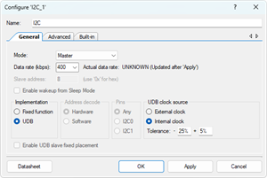
- Configure the I2C (I2C_1):
- Click on the I2C_1 component in the schematic.
- Rename the component to I2C to represent its connection to the I2C bus.
- Select Implementation to ☉ UDB.
- Select the ☉ Internal clock to use the internal clock source.
- Change the Data rate (kbps) to 400 kbps.
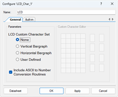
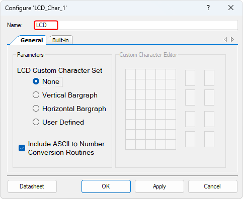
- Configure the Character LCD (LCD_Char_1):
- Click on the LCD_Char_1 component in the schematic.
- Rename it to LCD for clarity and easier identification.
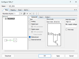
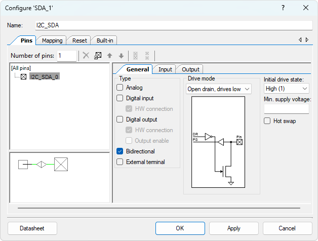
- Configure the Digital Output Pin (SDA_1):
- Click on the SDA_1 component in the schematic.
- Rename it to I2C_SDA.
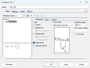
- Configure the Digital Output Pin (SCL_1):
- Click on the SCL_1 component in the schematic.
- Rename it to I2C_SCL.
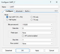
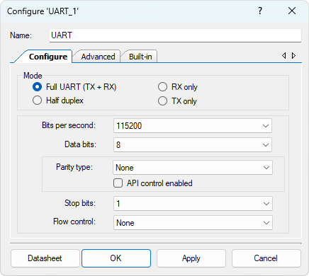
- Configure the UART (UART_1):
- Select the UART_1 component.
- Rename the component to UART.
- Set the following UART parameters:
- Mode: Full UART (TX + RX)
- Baud Rate: 115200 bps
- Parity: None
- Stop Bits: 1
- Flow Control: None
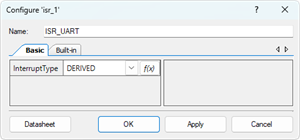
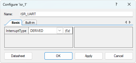
- Configure the Interrupt (isr_1):
- Select the isr_1 component.
- Rename the component to ISR_UART.
- Configure the Digital Input Pin (Rx_1):
- Select the Rx_1 component.
- Rename the component to UART_Rx to indicate its role as the UART receive pin.
- Configure the Digital Input Pin (Tx_1):
- Select the Tx_1 component.
- Rename the component to UART_Tx to indicate its role as the UART transmit pin.


Wiring
- Remove unused Components
- Delete the existing Clock_1 component and the wire connected to the I2C component.
- The I2C will use its internal clock source, so no external clock is required.
- Delete the existing RST_1 component connected to the reset pin of the I2C component.
- Delete the existing Clock_1 component and the wire connected to the I2C component.
- Connect Reset Pins
- Connect the Logic Low '0' signal to the reset pin of both the I2C and UART components.
- Connect UART Interrupt
- Connect the ISR_UART component to the rx_interrupt output of the UART component.
- This ensures that the interrupt service routine (ISR) is triggered whenever a character is received via UART.
After completing these steps, the TopDesign.cysch file will show the updated design with the renamed I2C, LCD, ISR_UART and UART components properly set up for I2C and UART communication.
Pin Assignment
| Device | Port.Pin | Direction | Drive Mode |
|---|---|---|---|
Generate Application
- From the menu bar, click Build ➤ Generate Application.
- This command instructs PSoC Creator to generate the necessary source code files based on the components you have placed and configured in the TopDesign.cyschschematic.
Configure Interrupt Priority
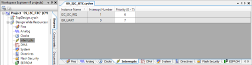
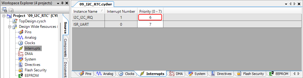
- In the Workspace Explorer window, open Design Wide Resources ➤ Interrupts.
- Locate I2C_I2C_IRQ in the interrupt list.
- Set its Priority value to 6.
Template Firmware Code
main.c
#include "project.h"
#include <stdio.h>
#include <stdlib.h>
#include <stdint.h>
#include <stdbool.h>
#include <string.h>

bool I2C_ReadBytes(uint8_t slaveAddr, uint8_t registerNum, int dataLength, uint8_t *userArray);
bool I2C_WriteBytes(uint8_t slaveAddr, uint8_t registerNum, int dataLength, uint8_t *userArray);

#define DS3231_SLAVE_ADDR       0x68    // 0b_110_1000 = 0x68

#define DS3231_REG_SECONDS      0x00
#define DS3231_REG_MINUTES      0x01
#define DS3231_REG_HOURS        0x02
#define DS3231_REG_DAY          0x03
#define DS3231_REG_DATE         0x04
#define DS3231_REG_MONTH        0x05
#define DS3231_REG_YEAR         0x06
#define DS3231_REG_CONTROL      0x0E
#define DS3231_REG_STATUS       0x0F

#define DS3231_BIT_12HRFORMAT   0x40
#define DS3231_BIT_24HRFORMAT   0x00
#define DS3231_BIT_AM           0x00
#define DS3231_BIT_PM           0x20
#define DS3231_BIT_CTRL_EOSC    0x80    // 0x0E bit7
#define DS3231_BIT_STAT_OSF     0x80    // 0x0F bit7

#define DS3231_DAY_SUN          0x01
#define DS3231_DAY_MON          0x02
#define DS3231_DAY_TUE          0x03
#define DS3231_DAY_WED          0x04
#define DS3231_DAY_THR          0x05
#define DS3231_DAY_FRI          0x06
#define DS3231_DAY_SAT          0x07


#define DEC2BCD(dec) ( (uint8_t)((((dec) / 10U) << 4) | ((dec) % 10U)) )
#define BCD2DEC(bcd) ( (uint8_t)((((bcd) >> 4) * 10U) + ((bcd) & 0x0FU)))

typedef enum STATES{
    S_IDLE,
    S_RECEIVING
} STATES;

#define START_CHAR  '#'
#define STOP_CHAR   ';'

volatile bool   IsRtcError = false;

CY_ISR_PROTO(myISR_UART);

bool    DS3231_InitCheck();
bool    DS3231_ReadTime(uint8_t out[7]);
void    DecodeAndDisplay(const uint8_t b[7]);
int main(void)
{
    uint8_t buf[7];

    CyGlobalIntEnable; /* Enable global interrupts. */

    /* Place your initialization/startup code here (e.g. MyInst_Start()) */

    IsRtcError = DS3231_InitCheck();

    for(;;)
    {
        /* Place your application code here. */
        if (!IsRtcError){
            if (DS3231_ReadTime(buf)){
                DecodeAndDisplay(buf);
            }
        }
        CyDelay(1000);
    }
}
//------------------------------------------------------------------------------
bool DS3231_InitCheck()
{
    // Control (0x0E): ensure EOSC=0 (oscillator enabled)

    // Status (0x0F): if OSF=1, time is invalid → prompt user to set time

}
//------------------------------------------------------------------------------
bool DS3231_ReadTime(uint8_t out[7])
{

}
//------------------------------------------------------------------------------
void DecodeAndDisplay(const uint8_t b[7])
{
    static const char * const weekDay[] = {"SU","MO","TU","WE","TH","FR","SA"};
    uint8_t     ss, mm, hh, day, DD, MM, YY;
    uint16_t    YYYY;
    bool        isPm = false;
    char        str[41];

}
//------------------------------------------------------------------------------
#define _I2C_WRITE_MODE  0
#define _I2C_READ_MODE   1

bool I2C_ReadBytes(uint8_t slaveAddr, uint8_t registerNum, int dataLength, uint8_t *userArray)
{
    uint8_t status;
    bool    noError = false;
    int     i;

}
//------------------------------------------------------------------------------
bool I2C_WriteBytes(uint8_t slaveAddr, uint8_t registerNum, int dataLength, uint8_t *userArray)
{
    uint8_t status;
    bool    noError = false;
    int     i;

}
//------------------------------------------------------------------------------
#define CMD_BUF_SIZE    100

CY_ISR(myISR_UART)
{
    static STATES       state = S_IDLE;
    static char         cmdBuf[CMD_BUF_SIZE];
    static volatile int cmdLen = 0;

    char                ch;

}
/* [] END OF FILE */
Exercises
Exp #0 DS3231 RTC Oscillator Control and Status
Ensure the DS3231 oscillator is enabled and verify that the date/time values are valid before use.
Registers of Interest
- 0x0E – Control Register
- Bit 7 (EOSC): Enable Oscillator (0 = oscillator enabled, 1 = disabled).
- 0x0F – Status Register
- Bit 7 (OSF): Oscillator Stop Flag (1 = oscillator stopped; date/time unreliable, 0 = normal operation).
Steps
- Enable Oscillator
- Read the Control register (0x0E).
- Ensure bit 7 (/EOSC) is cleared (0). If set, clear it to enable the oscillator.
- Check Oscillator Stop Flag
- Read the Status register (0x0F).
- If bit 7 (OSF) = 1, it means the RTC oscillator has stopped (e.g., due to power loss or first-time use).
- In this case:
- Display a message on the LCD, such as:
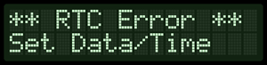
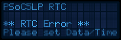
- Prevent normal operation until the user updates the RTC with a valid date/time via Exercise 2.
- Display a message on the LCD, such as:
- Clear OSF After Update
- Once a valid date/time is written to the RTC, clear the OSF bit by writing 0 to it.
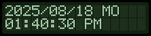
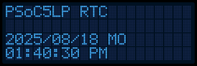
Exp #1 Dispaly Current Date and Time
Read the current date and time from the DS3231 RTC via I2C, decode the raw BCD-encoded register values, and display the information on the LCD in 12-hour format with AM/PM, refreshing once per second.
DS3231 RTC I2C Register Reference (00x00 ~ 0x06)
| Address | Register | Format / Notes |
|---|---|---|
| 0x00 | Seconds | BCD (00 ~ 59) |
| 0x01 | Minutes | BCD (00 ~ 59) |
| 0x02 | Hours | BCD with 12/24-hour format control:
|
| 0x03 | Day of Week | Values 1–7 (not 0-based). User-defined mapping (e.g., 1=SU, 2=MO … 7=SA). |
| 0x04 | Date (Day) | BCD (01 ~ 31) |
| 0x05 | Month/Century | BCD (01 ~ 12). Bit 7 = Century flag (0=20xx, 1=+100 years). |
| 0x06 | Year | Two-digit BCD (00–99). For this lab, assume 20xx (e.g., 25 → 2025). |
Key Concepts
- Year Handling:
- The RTC stores only two-digit years (00 ~ 99).
- Use the Month register bit 7 (Century bit) to distinguish centuries:
- 0 = 19xx or 20xx (implementation-defined, typically 20xx).
- 1 = +100 years (e.g., 2100–2199).
- For this lab, assume all years are 20xx (e.g., 0x25 → 25 → 2025).
- BCD Conversion:
- Each field is stored in BCD (binary-coded decimal). Example: 0x25 = 25.
- Create Macro Functions:
#define DEC2BCD(dec) (________)
#define BCD2DEC(bcd) (________)
- Day-of-Week Mapping:
- Values 1 ~ 7 (not zero-based).
- Map to labels: 1 = SU, 2 = MO, 3 = TU, 4 = WE, 5 = TH, 6 = FR, 7 = SA.
- Hours Format:
- The RTC can be in either 12-hour or 24-hour mode.
- For this lab, always display in 12-hour format with AM/PM.
- Bit 6 of the Hours register:
- 0 = 24-hour format (bits 5 ~ 4 hold 20h digit).
- 1 = 12-hour format; then Bit 5 = AM/PM flag (0 = AM, 1 = PM).
Steps
- Read RTC registers 0x00 ~ 0x06 via I2C in one burst read.
- Convert BCD values into decimal for seconds, minutes, hours, days, dates, months, and years.
- Process Hours:
- If RTC is in 24-hour mode (bit 6 = 0): convert BCD hours (00–23) into decimal, then convert to 12-hour format in software:
- If RTC is in 12-hour mode (bit 6 = 1), extract hours and use Bit 5 to determine AM/PM.
- Reconstruct the full year:
- Two-digit year + assumed century.
- Example: Year=0x25 → 25, Century=0 → 2025.
- Display on LCD in 12-hour format with AM/PM every second:
Hits
- I2C Access:
- Use the I2C Master APIs in PSoC Creator to read multiple bytes starting from register 0x00.
- The DS3231 stores time/date across 7 registers (0x00 ~ 0x06).
- BCD Conversion:
- Always convert before displaying.
- Example: 0x25 (BCD) → decimal 25.
- Year Handling:
- The year register (0x06) is only two digits (00 ~ 99).
- Assume 20xx when displaying.
- Example: 0x25 → 25 → display as 2025.
- Day of Week:
- Use a lookup table or switch-case to display a text label.
- LCD Output:
- Clear or overwrite the LCD before each update to prevent overlapping text.
- Debugging Tip:
- Before writing to the LCD, try sending the decoded values over UART to confirm your BCD conversions are correct.
Exp #2 Update Date and Time via UART
Receive formatted commands from the host PC, parse them, and update the DS3231 date and time registers over I2C. Convert all values into BCD format before writing.
UART Command Formats for Updating RTC:
| Command Format | Example | Description |
|---|---|---|
| #DATE:mm/dd/yy/day; | #DATE:03/15/25/SA; | Set date to March 15, 2025 (Saturday) using a 2-digit year. |
| #DATE:mm/dd/yyy/day; | #DATE:03/15/2025/SA; | Set date to March 15, 2025 (Saturday) using a 4-digit year (reduced to yy). |
| #TIME:hh:mm:ss; | #TIME:14:35:59; | Set time in 24-hour format (14:35:59 → 2:35:59 PM). |
| #TIME:hh:mm:ss:am; | #TIME:02:35:59:pm; | Set time in 12-hour format (2:35:59 PM). Case-insensitive for am/pm. |
Rules
- Date Handling:
- Month, day, year → convert to BCD.
- If the year is 4 digits, take yyyy % 100 to form a 2-digit BCD year.
- Day-of-week → map string (SU…SA) into RTC value 1 ~ 7.
- Time Handling:
- Parse hours, minutes, seconds.
- If a 12-hour format with AM/PM is provided:
- Save to DS3231 in 12-hour mode (set bit 6 = 1).
- Set bit 5 = 0 for AM, 1 for PM.
- Save hours (01 ~ 12) in BCD.
- If a 24-hour format is provided:
- Save to DS3231 in 24-hour mode (set bit 6 = 0).
- Hours encoded directly (00 ~ 23) in BCD.
- Minutes and seconds → always in BCD.
- I2C Write Sequence:
Write registers in order:- 0x00 Seconds
- 0x01 Minutes
- 0x02 Hours (with format bits set as above)
- 0x03 Day (1 ~ 7)
- 0x04 Date (BCD)
- 0x05 Month (BCD; century bit = 0 for 20xx)
- 0x06 Year (two-digit BCD)
- Verification:
- After writing, Exercise 1’s LCD loop should show the updated time/date in 12-hour format with AM/PM.
Hits
- Always convert decimal → BCD before writing to RTC.
- For 12-hour mode, validate that 1 ≤ hh ≤ 12. For 24-hour mode, 0 ≤ hh ≤ 23.
- Echo parsed results over UART for debugging.