EE3450-Tiva Lab 07: 4-Digit Seven-Segment Timer Controller
Objectives
Required Reading Materials
- Lesson 07: Create an ARM C Application with Keil μVision MDK-ARM
- Lesson 09: GPIO Ports and Configurations
- Set, Clear, Toggle, and Check Bit Value in C
- Polling Method in Embedded Programming
Overview
4-Digit Seven-Segment Display
The 4-digit seven-segment display consists of 12 pins. Among these pins, 8 are assigned to the 8 LEDs present in each seven-segment display, which are responsible for segments A to G and the decimal point (DP). The remaining 4 pins represent the 4 digits from D1 to D4.
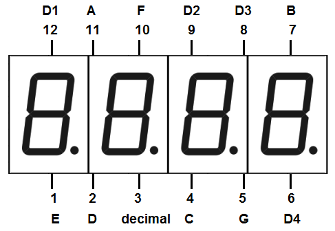
Each of the four digits present in the module has a common connection point. The same segment numbers in each digit are concatenated together, allowing each digit to be controlled independently, and reducing the number of required GPIO pins to 12 instead of 32.
Common Anode (CA)
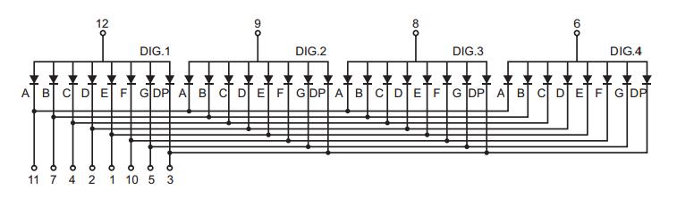
A common anode display has all the positive terminals (anode connections) of each digit connected together, There are four common pins for digits 1, 2, 3, and 4. To display a character on one of the digits, first, connect the common ping of the desired digit to a power source. Then, connect a suitable current limiting resistor between the cathode of the particular segment (a~g) and the ground to turn on that segment.
Common Cathode
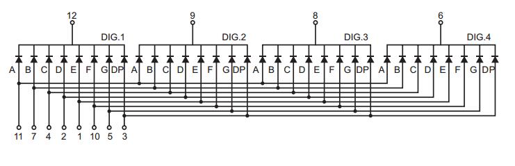
In a common cathode display, the cathode of each LED segment is connected to the negative terminal of the power supply, while the anodes of all LEDs in a digit are connected together. To display a character on a specific digit, you connect the common pin of that digit to the ground and apply a voltage to the desired segment's anode via a current-limiting resistor. This will turn on the corresponding LED segment on the selected digit.
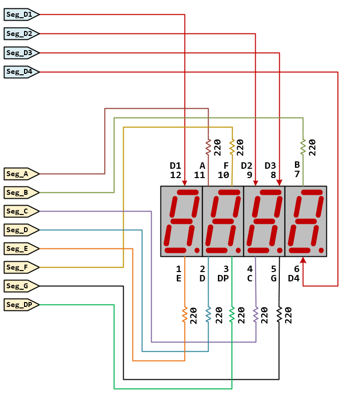
Circuit
Timer
You are designing a timer with the following functions:
- The timer has two switches: SW1 and SW2.
- SW1 starts and pauses the timer, while SW2 resets and stops the timer.
- The timer can count from 00:00 to 59:59, then stop.
The timer operation is as follows:
- Check the states of SW1 and SW2 every 20 ms.
- If SW2 is active, set both the minute and second digits to 0 and pause the timer
- otherwise, if SW1 is pressed, toggle the pause variable
- Display one digit of the seven-segment every 5 ms.
- Toggle the decimal point (Seg_DP) of the second digit (D2) every 500 ms
- Increase the second digit by 1 every 1000 ms, and update the minute digit accordingly.
- If the timer reaches 59:59, pause the timer.
Pin configurations
| Device | Port.Pin | Signal Type | Module | Direction | Drive Mode |
|---|---|---|---|---|---|
Lab Template Firmware Source Code
This section provides the template firmware source code for the TM4C123G and TM4C1294 platforms used in these laboratory exercises. Explanatory notes are included to help readers understand the purpose and operation of each major part of the program.
The provided code is intended as a reference starting point and may be copied into the project as needed. Since the template is not a final, complete program, it should be reviewed and modified to meet the requirements of each experiment. Unnecessary statements may be commented out, and appropriate comments should be added to clearly document the program structure and implementation details.