PSoC5LP Lab 03: UART-Based LED Control and Switch State Monitoring
Objective
- Configure and test a UART (8‑N‑1) on PSoC 5LP at 115200 bps.
- Map I/O pins and use digital input/output components in PSoC Creator.
- Implement framed, case‑insensitive command parsing: #<CMD>;.
- Debounce a pushbutton and report press/release events over UART.
- Interoperate with a PC serial terminal to validate transmit/receive paths.
Overview
In this lab, you will explore how to use the UART interface for two-way communication between a microcontroller and a host PC. The lab is divided into two main exercises:
- Exercise 1: You will configure the system so that the host PC can send text-based commands through the UART to control an LED (LED1). The microcontroller will process the received commands using an interrupt-driven state machine and execute the corresponding action (turning LED1 on or off).
- Exercise 2: You will extend the functionality to allow the microcontroller to send messages back to the host PC whenever a switch (SW1) is pressed or released. This will be done using a software edge detection method, so that the system reliably detects switch state changes and reports them as "SW1 is pressed" or "SW1 is released" messages.
Through these exercises, you will gain hands-on experience in configuring digital input/output pins, implementing UART communication, handling interrupts, and designing state machines for command processing and edge detection. Together, these skills form a strong foundation for building interactive embedded systems with real-time input and output control.
.
Required Reading Materials
- Lesson KB 01: Create a PSoC Project using PSoC Creator
- Universal Asynchronous Receiver-Transmitter (UART)
- Input Signal Edge Detection using Software
- PSoC Creator Component Datasheet:
- Windows software for serial communication:
- Termite: [Termite Website] Download Termite 3.4: [exe] [zip]
- PuTTY.exe: http://www.chiark.greenend.org.uk/~sgtatham/putty/latest.html
Required Components
| picture 64x64 | description | × quantity |
| × 1 | ||
| × 1 |
Circuit / Schematic
Procedure
Creating a New Project
- Launch PSoC Creator.
- Got to File ➤ Open Project ➤ Project/Workspace.
- Open the PSoC5LP workspace in the EE4450 folder.
- After PSoC Creator opens the workspace, right-click on Workspace 'PSoC5LP' in the Workspace Explorer and select Add ➤ New Project...
- Select the correct PSoC5LP device model number, use the "Empty schematic" template, and enter the project name 03_UART_GPIO.
Adding PSoC Creator Components
In this section, we will add the necessary components to the schematic (TopDesign.cysch) in PSoC Creator
- Add a Digital Input Pin:
- Open the component catalog and go to the Ports and Pins category.
- Drag and drop a
 Digital Input Pin onto the schematic.
- Add a Digital Output Pin:
- From the same Ports and Pins category, select Digital Output Pin.
- Drag and drop it onto the schematic.
- From the same Ports and Pins category, select
- Add a UART:
- Open the Communication category.
- Drag and drop a UART onto the schematic.
- Add an Interrupt:
- Go to the System category.
- Drag and drop an
 Interrupt onto the schematic.
- Add a Logic '0':
- Under the Digital category.
- Drag and drop a Logic Low '0' onto the schematic.
After completing these steps, the schematic will include all necessary components — Digital Input Pin, Digital Output Pin, UART, Logic ‘0’, and Interrupt — ready for configuration and connection in the next stage.
Configure the Components
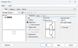
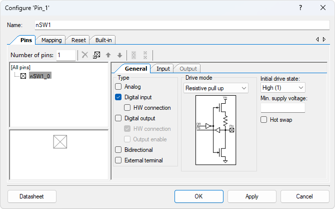
- Configure the Digital Input Pin (Pin_1):
- In the schematic, select the Pin_1 component.
- Rename the component to nSW1 to indicate its connections to a switch.
- Set the Drive Mode to Resistive Pull-Up, which ensures the pin defaults to high when not pressed.
- Uncheck the box for HW connection to disable the hardware connection, as shown in the diagram.
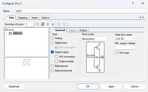
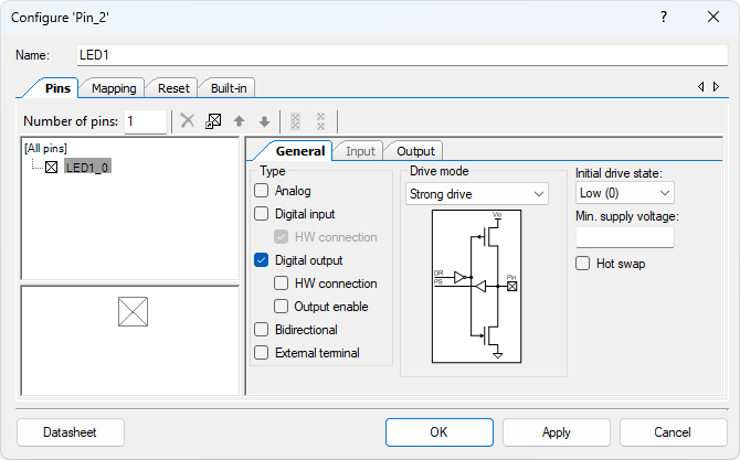
- Configure the Digital Output Pin (Pin_2):
- Select the Pin_2 component.
- Rename the component to LED1, showing that it drives the LED.
- Uncheck the HW connection box so that the LED will be controlled by software.
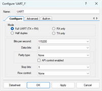
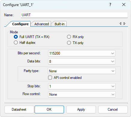
- Configure the UART (UART_1):
- Select the UART_1 component.
- Rename the component to UART.
- Set the following UART parameters:
- Mode: Full UART (TX + RX)
- Baud Rate: 115200 bps
- Parity: None
- Stop Bits: 1
- Flow Control: None
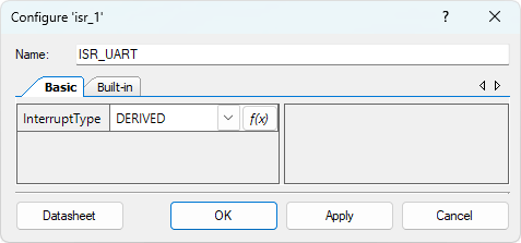
- Configure the Interrupt (isr_1):
- Select the isr_1 component.
- Rename the component to ISR_UART.
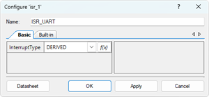
- Connect the ISR_UART to the rx_interrupt output of the UART component. This allows the interrupt service routine to be triggered whenever a character is received via UART.
- Configure the Digital Input Pin (Rx_1):
- Select the Rx_1 component.
- Rename the component to UART_Rx to indicate its role as the UART receive pin.
- Configure the Digital Input Pin (Tx_1):
- Select the Tx_1 component.
- Rename the component to UART_Tx to indicate its role as the UART transmit pin.
- Connect Reset Pin:
- Connect the Logic Low '0' signal to the reset pin on the UART component.
- This configuration disables the reset function of the UART, allowing it to remain enabled during operation.
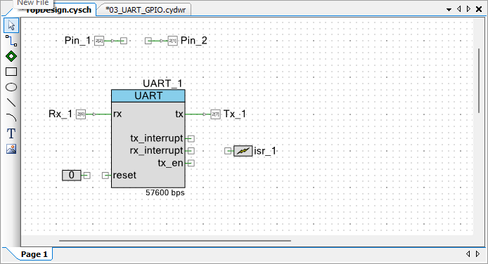
The new TopDesign.cysch file is shown below:
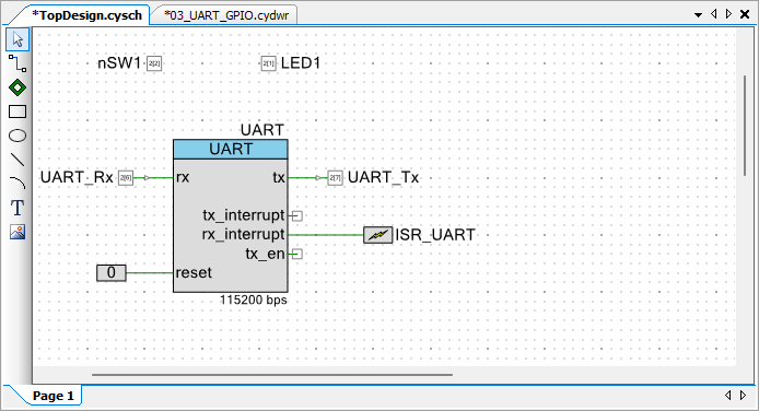
The UART communication allows a host PC (using Termite or similar terminal software) to send specific commands to the microcontroller. The microcontroller will interpret these commands and toggle LED1 accordingly. The received data will be handled by an Interrupt Service Routine (ISR), while a state machine is used to process complete command strings.
Pin Assignment
| Device | Port.Pin | Direction | Drive Mode |
|---|---|---|---|
Template Firmware Code
main.c
#include "project.h"
#include <stdio.h>
#include <stdlib.h>
#include <stdint.h>
#include <stdbool.h>
#include <string.h>

typedef enum STATES{
    S_IDLE,
    S_RECEIVING
} STATES;

#define START_CHAR  '#'
#define STOP_CHAR   ';'

CY_ISR_PROTO(myISR_UART);

int main(void)
{
    bool        curSw1;
    bool        preSw1 = true;

    CyGlobalIntEnable; /* Enable global interrupts. */

    /* Place your initialization/startup code here (e.g. MyInst_Start()) */

    for(;;) {
        /* Place your application code here. */

        CyDelay(20);    // Apply a 20 ms delay for switch debouncing
    }
}
//------------------------------------------------------------------------------
#define CMD_BUF_SIZE    100
char    CmdBuf[CMD_BUF_SIZE];

CY_ISR(myISR_UART)
{
    static STATES   state = S_IDLE;
    static int      cmdLength;
    char            ch;

}
/* [] END OF FILE */
Exercises
Exp #1 Sending Commands to Control LED1
You will implement UART-based command control for LED1. The system receives text-based commands from the terminal software and toggles the LED accordingly.
Command Table:
| Command | Description |
|---|---|
| #LED1ON; | Turn on LED1 |
| #LED1OFF; | Turn off LED1 |
Steps
Step1:
Implement a UART Receive Interrupt in your firmware and design a state machine to process commands:
- Use the UART ISR to capture incoming characters one by one and store them in a buffer.
- If the received character is the start character #, transition into the receiving state.
- In this state, ensure there is enough buffer space to save subsequent characters.
- Continue saving incoming characters until the termination character ; is received.
- Once the complete command string has been captured, compare it with the valid commands listed in the table above.
- If the command matches, perform the corresponding action (turn LED1 on or off).
- If the command does not match, ignore it or handle it as an invalid command.
Step 2: (Testing):
Open Tera Term (or another serial terminal) and connect to the correct COM port with the following settings:
- Baud Rate: 115200
- Data: 8 bits
- Parity: None
- Stop: 1 bit
- Flow Control: None
Hints:
- Use UART ISR (CY_ISR) to handle received characters efficiently.
- Maintain a buffer array to store incoming characters until ; is received.
- Implement the state machine with states such as S_IDLE and S_RECEIVING.
- Use strcmp() or similar string comparison functions to match the received command string.
- Always test using both valid and invalid commands to verify robustness.
By completing this lab, you will gain hands-on experience with UART communication, interrupt handling, and state machine design, which are essential skills in embedded system development.
Exp #2 Detecting Switch Events and Sending Messages
In this exercise, you will extend the functionality of the system to detect switch presses and releases (SW1) and send corresponding messages to the host PC via UART. Instead of polling, you will use a software edge detection method to detect the rising and falling edges of the input signal.
Behavior:
- When SW1 is pressed (falling edge), the microcontroller sends the string:
SW1 is pressed - When SW1 is released (rising edge), the microcontroller sends the string:
SW1 is released
Steps
- In the firmware, periodically read the switch input state.
- Implement software edge detection (refer to edge detection method):
- Keep track of the previous state of SW1.
- Compare the current state with the previous state.
- If the state transitions from high → low (falling edge), send "SW1 is pressed" via UART.
- If the state transitions from low → high (rising edge), send "SW1 is released" via UART.
- Update the previous state after each comparison to ensure correct edge detection.
Hints
- Use UART PutString() API to send predefined strings to the terminal.
- Edge detection works best inside a timer interrupt or main loop with periodic sampling.
- Debounce the switch in software if you notice multiple triggers on a single press.
- Test by pressing and releasing SW1 several times, ensuring messages are reliably received on the terminal.
✅ By completing this exercise, you will gain experience in edge detection, input event handling, and message transmission, further strengthening your embedded system design skills.