PSoC5LP Lab 14: Walking Man on MAX7219 LED Dot Matrix Module
Objectives
By completing this lab, you will be able to:
- Connect and control the MAX7219 LED Dot Matrix Module using the PSoC 5LP’s SPI interface.
- Configure the MAX7219 registers to operate in 8×8 dot-matrix mode, including scan limit, decode mode, shutdown mode, and brightness settings.
- Create 8×8 bitmap images and send them to the LED matrix using SPI row-data transfers.
- Implement a multi-frame “walking man” animation similar to the pedestrian symbol used in traffic light systems.
- Develop reusable firmware functions to write rows, display bitmap frames, and control animation timing.
- Adjust animation speed and verify smooth playback on the LED dot matrix display.
Overview
In this lab, you will create the familiar “walking man” animation used in pedestrian traffic light systems. These animated icons indicate when it is safe for pedestrians to cross and are typically implemented using LED matrix modules. By recreating this animation on an 8×8 LED Dot Matrix Display, you will learn how simple bitmap frames and timed transitions are combined to produce motion effects similar to real-world traffic signals.
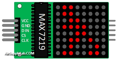
The display is controlled by the MAX7219 LED Matrix Driver, a dedicated IC designed for 8×8 LED arrays. The MAX7219 manages multiplexing, LED current control, brightness, and row scanning, enabling you to display images without manually refreshing individual LEDs. Each row of the matrix corresponds to one of the MAX7219’s digit registers, making it simple to send 8-byte bitmap patterns.
Communication between the PSoC 5LP and the MAX7219 uses the SPI protocol, which operates as a high-speed shift-register interface. Data is clocked into the MAX7219 one bit at a time and then latched into internal registers when the Slave Select (SS) signal is toggled. By writing eight bytes—one per row—you can update a complete 8×8 image on the matrix.
To produce animation, multiple bitmap frames representing different walking poses are stored in firmware. These frames are sent to the MAX7219 sequentially, with a short delay between each one, creating a smooth walking movement similar to the pedestrian signals used at crosswalks.
Through this lab, you will gain practical experience with LED matrix display control, SPI serial communication, and rendering animation on embedded systems.
Required Reading Materials
Required Components
If you use the Cypress CY8CKIT-059 Kit, the onboard LED and button will be used in this lab.
The following components are required for this lab.
| MAX7219 LED Dot Matrix Module | x 1 | |
| Resistor 200ohm (if using an external LED) | x 1 | |
| Red LED (or onboard LED) | x 1 |
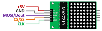
Circuit / Schematic
Procedure
Creating a New Project
- Launch PSoC Creator.
- Got to File ➤ Open Project ➤ Project/Workspace.
- Open the PSoC5LP workspace in the EE4450 folder.
- After PSoC Creator opens the workspace, right-click on Workspace 'PSoC5LP' in the Workspace Explorer and select Add ➤ New Project….
- Select the correct PSoC5LP device model number, use the "Empty schematic" template, and enter the project name 14_LedDotMatrix.
Adding Components in PSoC Creator
Open the "TopDesign.cysch" Schematic File, add the following components:
- Add an SPI Master (Full Duplex) Component:
- In the Component Catalog, expand Communications → SPI.
- Select
 SPI Master Full Duplex mode Macro and drag it into the schematic.
- Add Two Digital Output Pins:
- In the Component Catalog, open Ports and Pins.
- Drag two Digital Output Pin components into the schematic.
- Add a Logic Low '0' component:
- Navigate to Digital → Logic in the Component Catalog.
- Locate Logic Low '0' and place it onto the schematic.
After adding these components, you may proceed to configure each one as described below.
Configuring the Components
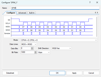
- Configure the SPIM_1 Master Component:
- Click the SPIM_1 component on the schematic.
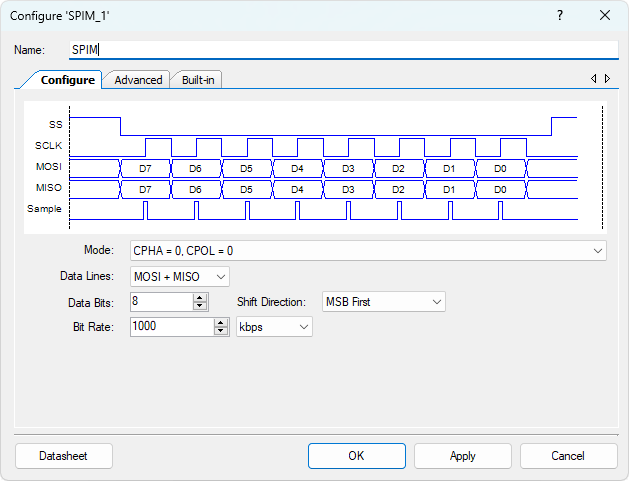
- Rename it to SPIM (indicating "SPI Master").
- Set the SPI Mode to Mode 0:
- CPHA = 0
- CPOL = 0.
- Configure Digital Output Pin (Pin_1):
- Select the Pin_1 component.
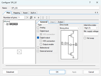
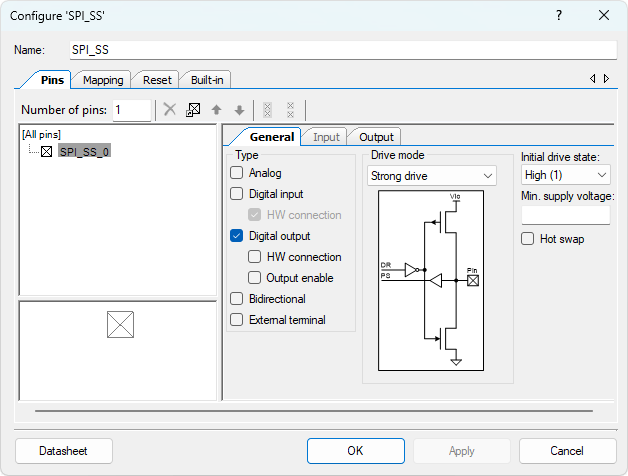
- Rename it to SPI_SS (Slave-Select signal).
- Uncheck ☐ HW connection to ensure the pin is software-controlled.
- Change the Initial drive state to High (1).
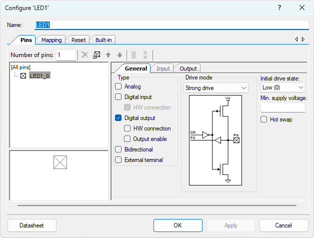
- Configure the Digital Output Pin (Pin_2):
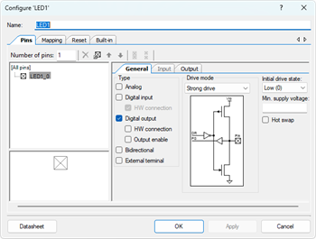
- Select the Pin_2 component.
- Rename it to LED1.
- Uncheck ☐ HW connection so that firmware controls the LED output.
- Rename All Pins Connected to the SPIM Component
Rename the auto-generated SPI pins to meaningful signal names:Original Name New Name MISO_1 SPI_MISO MOSI_1 SPI_MOSI SCLK_1 SPI_SCLK
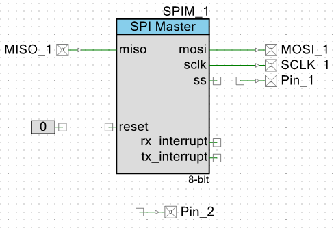
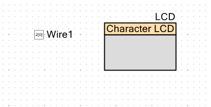
Wiring
Connect the Reset Pin
Attach the Logic Low '0' component to the Reset input pin of the SPIM block to ensure the SPI Master remains enabled during operation.
The new TopDesign.cysch file is shown below:
Pin Assignment
| Device | Port.Pin | Direction | Drive Mode |
|---|---|---|---|
Building and Programming the Firmware
Next, implement two functions that will handle communication with the SPI slave device:
Source Code for MAX7219
max7219.h
#ifndef __MAX7219_H
#define __MAX7219_H

#include <stdio.h>
#include <stdlib.h>
#include <stdint.h>
#include <stdbool.h>
#include "project.h"

#define _MAX7219_REG_NOOP           0x00
#define _MAX7219_REG_DIGIT0         0x01
#define _MAX7219_REG_DIGIT1         0x02
#define _MAX7219_REG_DIGIT2         0x03
#define _MAX7219_REG_DIGIT3         0x04
#define _MAX7219_REG_DIGIT4         0x05
#define _MAX7219_REG_DIGIT5         0x06
#define _MAX7219_REG_DIGIT6         0x07
#define _MAX7219_REG_DIGIT7         0x08
#define _MAX7219_REG_DECOD_MODE     0x09
#define _MAX7219_REG_INTENSITY      0x0A
#define _MAX7219_REG_SCAN_LIMIT     0x0B
#define _MAX7219_REG_SHUTDOWN       0x0C
#define _MAX7219_REG_DISPLAYTEST    0x0F

#define _MAX7219_SHUTDOWN_ENABLE    0x00
#define _MAX7219_SHUTDOWN_NORMAL    0x01
#define _MAX7219_DECODE_MODE_NONE   0x00
#define _MAX7219_SCAN_LIMIT_0TO7    0x07
#define _MAX7219_DISPLAYTEST_ON     0x01
#define _MAX7219_DISPLAYTEST_OFF    0x00

void max7219_init();
void max7219_clear();
void max7219_show_frame(const uint8_t frame[8]);

#endif
max7219.c
#include "max7219.h"
#include "spi_function.h"
//------------------------------------------------------------------------------
// Function: max7219_init
// Description:
//   Initialize MAX7219 for 8×8 LED Dot Matrix operation.
//   Students must configure Shutdown, Decode Mode, Scan Limit, Intensity,
//   Display Test, and return to Normal Operation.
//   Follow the required initialization sequence provided in the lab description.
//------------------------------------------------------------------------------
void max7219_init()
{
    uint8_t data;

    // 1. Enter Shutdown Mode
    // Hint: Write the shutdown-register with the "OFF" value.
    // Purpose: Ensure LED matrix is blank during setup.
    SPI_WriteReg( ??? , 1 , &data );

    // 2. Disable Code-B Decode Mode
    // Hint: Dot-matrix mode requires NO decode.
    // Hint: Set all bits OFF for raw 8-bit control.
    SPI_WriteReg( ??? , 1 , &data );

    // 3. Set Scan Limit to use all 8 rows (0–7)
    // Hint: Use the constant from your header file (0–7 enabled).
    SPI_WriteReg( ??? , 1 , &data? );

    // 4. Set LED Intensity (Brightness)
    // Hint: Valid range is 0x00~0x0F.
    // Hint: Pick a medium brightness value for testing.
    SPI_WriteReg( ??? , 1 , &data );

    // 5. Optional Display Test
    // Hint: Turn ON test-mode first, delay, then turn OFF.
    SPI_WriteReg( ??? , 1 , &data );   // test ON
    // CyDelay(1000);
    SPI_WriteReg( ??? , 1 , &data );   // test OFF

    // 6. Exit Shutdown → Enter Normal Operation
    // Hint: Write “normal operation” value to Shutdown Register.
    SPI_WriteReg( ??? , 1 , &data );

    // 7. Clear display before drawing any animation frame
    max7219_clear();
}

//------------------------------------------------------------------------------
// Function: max7219_clear
// Description:
//   Clears the entire 8×8 display by writing 0x00 to all digit registers.
//   Each digit register corresponds to a row in the LED matrix.
//------------------------------------------------------------------------------
void max7219_clear()
{
    int     i;
    uint8_t data = 0;

    // Hint: Loop through all 8 digit registers
    for (row = 0; row < 8; row++) {
        // Hint: Register address increases from DIGIT0 to DIGIT7
        SPI_WriteReg( ??? + row, 1, &data );
    }
}
//------------------------------------------------------------------------------
// Function: max7219_show_frame
// Description:
//   Show one 8×8 animation frame.
//   Each element in frame[] is one row (8 bits = 8 LEDs).
//------------------------------------------------------------------------------
void max7219_show_frame(const uint8_t frame[8])
{
    uint8_t row;

    for (row = 0; row < 8; row++) {
        // Hint: Each frame[row] must be written to the corresponding DIGIT register.
        SPI_WriteReg( ??? + row, 1, (uint8_t*)&frame[row] );
    }
}
//------------------------------------------------------------------------------
Template Code for Walking Man Animation Array
Use the following template to create your own 8-frame animation. Each frame contains 8 rows, and each row is an 8-bit pattern (bit7 = left, bit0 = right). Replace the 0b00000000 rows with your custom pixel patterns.
Animation Bitmap Template (animationMatrix.h)
//------------------------------------------------------------------------------
// 8-Frame Walking Man Animation (More detailed / smoother walking motion)
// Each frame uses 8 rows of 8 bits.
//------------------------------------------------------------------------------
const unsigned uint8_t Walking_Man[8][8] = {
    // Frame 0: Standing (initial position)
    {
        0b00000000, // Row 0
        0b00000000, // Row 1
        0b00000000, // Row 2
        0b00000000, // Row 3
        0b00000000, // Row 4
        0b00000000, // Row 5
        0b00000000, // Row 6
        0b00000000  // Row 7
    },
    // Frame 1: Right leg forward
    {
        0b00000000, // Row 0
        0b00000000, // Row 1
        0b00000000, // Row 2
        0b00000000, // Row 3
        0b00000000, // Row 4
        0b00000000, // Row 5
        0b00000000, // Row 6
        0b00000000  // Row 7
    },
    // Frame 2: Standing (transition back)
    {
        0b00000000, // Row 0
        0b00000000, // Row 1
        0b00000000, // Row 2
        0b00000000, // Row 3
        0b00000000, // Row 4
        0b00000000, // Row 5
        0b00000000, // Row 6
        0b00000000  // Row 7
    },
    // Frame 3: Left leg forward (begin)
    {
        0b00000000, // Row 0
        0b00000000, // Row 1
        0b00000000, // Row 2
        0b00000000, // Row 3
        0b00000000, // Row 4
        0b00000000, // Row 5
        0b00000000, // Row 6
        0b00000000  // Row 7
    },
    // Frame 4: Left leg forward (extended stride)
    {
        0b00000000, // Row 0
        0b00000000, // Row 1
        0b00000000, // Row 2
        0b00000000, // Row 3
        0b00000000, // Row 4
        0b00000000, // Row 5
        0b00000000, // Row 6
        0b00000000  // Row 7
    },
    // Frame 5: Transition stride
    {
        0b00000000, // Row 0
        0b00000000, // Row 1
        0b00000000, // Row 2
        0b00000000, // Row 3
        0b00000000, // Row 4
        0b00000000, // Row 5
        0b00000000, // Row 6
        0b00000000  // Row 7
    },
    // Frame 6: Leg crossing transition
    {
        0b00000000, // Row 0
        0b00000000, // Row 1
        0b00000000, // Row 2
        0b00000000, // Row 3
        0b00000000, // Row 4
        0b00000000, // Row 5
        0b00000000, // Row 6
        0b00000000  // Row 7
    },
    // Frame 7: Return to neutral walking stance
    {
        0b00000000, // Row 0
        0b00000000, // Row 1
        0b00000000, // Row 2
        0b00000000, // Row 3
        0b00000000, // Row 4
        0b00000000, // Row 5
        0b00000000, // Row 6
        0b00000000  // Row 7
    }
};
//------------------------------------------------------------------------------
These functions manage register-level read and write operations over the SPI interface at the register level.
Firmware Code (main.c)
/* ========================================
 *
 * © 2024 AirSupplyLab. All rights reserved.
 * Unpublished, licensed software.
 *
 * This software contains confidential and proprietary
 * information owned by AirSupplyLab.com.
 *
 * ========================================
*/
#include "project.h"
#include <stdlib.h>
#include <stdio.h>
#include <stdint.h>
#include <stdbool.h>
#include "spi_function.h"
#include "max7219.h"
#include "animationMatrix.h"

// The animation array should be declared in the "animationMatrix.h" file

//------------------------------------------------------------------------------
// main()
// Description:
//   Firmware entry point for the LED Matrix Walking-Man animation.
//   You must insert the animation loop inside the infinite for(;;) loop.
//------------------------------------------------------------------------------
int main(void)
{
    uint8_t frame = 0;   // Frame index for the animation sequence

    CyGlobalIntEnable;   /* Enable global interrupts. */

    // ----------------------------------------------------------
    // Hardware Initialization
    // ----------------------------------------------------------

    // Ensure Slave-Select (SS) is in the inactive state (HIGH) before SPI communication begins.
    SPI_SS_Write(1);

    // Start the SPI Master component
    SPIM_Start();

    // Clear TX/RX FIFOs to ensure clean SPI operation
    SPIM_ClearFIFO();

    // Initialize MAX7219 registers:
    // - Disable decode mode
    // - Set scan limit
    // - Exit shutdown mode
    // - Set brightness
    // - Clear screen
    max7219_init();

    // Wait briefly before starting animation
    CyDelay(1000);

    // ----------------------------------------------------------
    // Application Loop
    // ----------------------------------------------------------
    for (;;)
    {
        // ------------------------------------------------------
        // LED1 Heartbeat (Blinking LED)
        // Purpose:
        //   LED1 blinks every loop iteration to confirm your
        //   firmware is running correctly on the PSoC board.
        // ------------------------------------------------------
        LED1_Write(!LED1_Read());  // Toggle LED1

        /* ------------------------------------------------------
         * TODO: IMPLEMENT THE ANIMATION HERE
         *
         * 1. Display one frame of the Walking_Man[] array.
         *    - You must call your display function
         *      (e.g., max7219_show_frame(Walking_Man[frame]) )
         *
         * 2. Insert a 100 ms delay between frames.
         *      CyDelay(100);
         *
         * 3. Advance to the next frame.
         *
         * 4. Ensure the frame index loops from 0 back to 7.
         *
         * ------------------------------------------------------
         */
    }
}
//------------------------------------------------------------------------------
/* [] END OF FILE */