Tiva Lab Lab 02: Street Traffic Light
This lab focuses on developing a street traffic light controller using the TI Tiva C Series microcontroller. In this experiment, you will extend basic LED control techniques to simulate a real-world traffic signal system. By integrating multiple LEDs and programming a timed sequence, you will gain hands-on experience in managing concurrent outputs, understanding state transitions, and applying delay-based timing in embedded systems.
Level: ![]()
Objective
- Understand the fundamentals of microcontroller programming and circuit design.
- Develop a traffic light control system with specified timings.
- Practice programming I/O interfaces.
- Learn debugging and testing of embedded systems.
Required Reading Materials
- Lesson 07: Create an ARM C Application with Keil μVision MDK-ARM
- Lesson 09: GPIO Ports and Configurations
- Set, Clear, Toggle, and Check Bit Value in C
- Polling Method in Embedded Programming
Components Required
| Component/Device | Description | Quantity |
|---|---|---|
| 220 Ω (red red brn gld / red red blk blk brn) | × 6 | |
| Red LED | × 2 | |
| Green LED | × 2 | |
| Blue LED | × 2 |
Background
Traffic light systems manage the flow of traffic at intersections. Students can learn about sequential logic, timing control, and embedded system programming basics by creating a model traffic light system. This project involves creating a simplified cross-road traffic management system using LEDs for North-South and East-West directions.
Circuit Diagram
Use diagrams to set up the LEDs with the microcontroller.
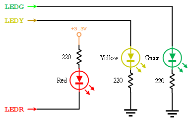
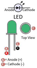
Figure 1: Circuit Diagram for Traffic Light
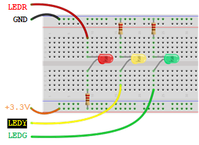
Figure 2: Connect the LEDs on the Breadboard
Pin Configuration Table
| Device | Port.Pin | Signal Type | Module | Direction | Drive Mode |
|---|---|---|---|---|---|
Crossroad Traffic Light System
For a complete simulation, construct two traffic lights:
- North-South Direction
- East-West Direction
Each light will follow the sequence:
- Green for 10 seconds
- Solid Yellow for 3 seconds
- Blinking Yellow for 2 seconds (500ms interval)
- Both directions turn red for a brief 1-second pause. Then, the cycle switches to another direction.
Procedure
- Circuit Setup
- The green and yellow LED's anode (longer leg) connects to the digital output, and the cathode (shorter leg) goes to the ground (GND) through a resistor.
- The red LED's anode (longer leg) connects to the power source through a resistor, and the cathode (shorter leg) connects to the digital output pin.
- Arrange the LEDs in two sets (North-South and East-West), each comprising a Red, Yellow, and Green LED.
- Programming
- Initialize the pins connected to the LEDs as OUTPUT in your code's Setup_GPIO() function.
- Follow the lab experiments session to implement the control code in the main() function
- Implement the timing sequence using DelayMs() for the specified durations.
- Testing and Debugging
- Upload the code to the microcontroller and observe the operation of the traffic light system.
- Verify lights change according to the sequence and timings.
- If necessary, adjust the code or connections to correct any issues.
Did You Know? Relating to their first installation in London in 1868, traffic lights represent one of the foundational robotic systems impacting society. The three-colored pattern we recognize today was first seen in 1920.
Example Firmware Code
Copy-paste the following code to your main.c file.
Lab Template Firmware Source Code
This section provides the template firmware source code for the TM4C123G and TM4C1294 platforms used in these laboratory exercises. Explanatory notes are included to help readers understand the purpose and operation of each major part of the program.
The provided code is intended as a reference starting point and may be copied into the project as needed. Since the template is not a final, complete program, it should be reviewed and modified to meet the requirements of each experiment. Unnecessary statements may be commented out, and appropriate comments should be added to clearly document the program structure and implementation details.
EK-TM4C123GXL LaunchPad - main.c
#include <stdio.h>
#include <stdlib.h>
#include <stdint.h>
#include <stdbool.h>

#include "TM4C123GH6PM.h"
#include "MyDefines.h"

void DelayMs(int ms);   // Software Delay Function
void Setup_GPIO(void);

int main(void)
{
    // Place your initialization/startup code here (e.g. Setup_GPIO() )
    Setup_GPIO();

    while (1) {
        // Place your application code here

    }
}
//------------------------------------------------------------------------------
/*
Device      Port.Pins       DIR     DriveMode
NS_GREEN
NS_YELLOW
NS_RED
EW_GREEN
EW_YELLOW
EW_RED

Port ____
*/

void Setup_GPIO(void)
{
    // Configure GPIOs
    // 1. Enable Clock to the GPIO Modules (SYSCTL->RCGCGPIO |= (_PORTs);)
    SYSCTL->RCGCGPIO |= (__);
    // allow time for clock to stabilize (SYSCTL->PRGPIO & (_PORTs))
    while ((SYSCTL->PRGPIO & (__)) != (__)) {};
    // 2. Unlock GPIO only PD7, PF0 on TM4C123G; PD7, PE7 on TM4C1294 (GPIOx->LOCK = 0x4C4F434B; and GPIOx->CR = _PINs;)
    //GPIOF->LOCK = 0x4C4F434B;   // Unlock for GPIOF
    //GPIOF->CR |= _PIN0;         // Commit for PIN0
    //GPIOF->LOCK = 0;
    // 3. Set Analog Mode Select bits for each Port (GPIOx->AMSEL = _PINs;)
    // 4. Set Port Control Register for each Port (GPIOx->PCTL = PMCn << _PTCL_PINn, check the PCTL table)
    // 5. Set Alternate Function Select bits for each Port (GPIOx->AFSEL = _PINs;)
    // 6. Set Output pins for each Port (Direction of the Pins: GPIOx->DIR = _PINs;)

    // 7. Set PUR bits (internal Pull-Up Resistor), PDR (Pull-Down Resistor), ODR (Open Drain) for each Port
    // 8. Set Digital ENable register on all port.pins (GPIOx->DEN = _PINs;)

}
//------------------------------------------------------------------------------
// Delay ms milliseconds (4167:50MHz TM4C123G CPU, 1605:16MHz TM4C123G CPU Clock)
void DelayMs(int ms)
{
    volatile int i, j;
    for (i = 0; i < ms; i++)
        for (j = 0; j < 4167; j++) {} // Do nothing for 1ms
}
EK-TM4C1294XL LaunchPad - main.c
#include <stdio.h>
#include <stdlib.h>
#include <stdint.h>
#include <stdbool.h>

#include "TM4C1294NCPDT.h"
#include "MyDefines.h"

void DelayMs(int ms);   // Software Delay Function
void Setup_GPIO(void);

int main(void)
{
    // Place your initialization/startup code here (e.g. Setup_GPIO() )
    Setup_GPIO();
    while (1) {
        // Place your application code here

    }
}
//------------------------------------------------------------------------------
/*
Device      Port.Pins       DIR     DriveMode
NS_GREEN
NS_YELLOW
NS_RED
EW_GREEN
EW_YELLOW
EW_RED

Port ____
*/
void Setup_GPIO(void)
{
    // Configure GPIOs
    // 1. Enable Clock to the GPIO Modules (SYSCTL->RCGCGPIO |= (_PORTs);)
    SYSCTL->RCGCGPIO |= (__);
    // allow time for clock to stabilize (SYSCTL->PRGPIO & (_PORTs))
    while ((SYSCTL->PRGPIO & (__)) != (__)) {};
    // 2. Unlock GPIO only PD7, PF0 on TM4C123G; PD7, PE7 on TM4C1294 (GPIOx->LOCK = 0x4C4F434B; and GPIOx->CR = _PINs;)
    // 3. Set Analog Mode Select bits for each Port (GPIOx->AMSEL = _PINs;)
    // 4. Set Port Control Register for each Port (GPIOx->PCTL = PMCn << _PTCL_PINn, check the PCTL table)
    // 5. Set Alternate Function Select bits for each Port (GPIOx->AFSEL = _PINs;)
    // 6. Set Output pins for each Port (Direction of the Pins: GPIOx->DIR = _PINs;)

    // 7. Set PUR bits (internal Pull-Up Resistor), PDR (Pull-Down Resistor), ODR (Open Drain) for each Port
    // 8. Set Digital ENable register on all port.pins (GPIOx->DEN = _PINs;)

}
//------------------------------------------------------------------------------
// Delay ms milliseconds (1605: 16MHz TM4C1294 CPU Clock)
void DelayMs(int ms)
{
    volatile int i, j;
    for (i = 0; i < ms; i++)
        for (j = 0; j < 1605; j++) {}   // // Do nothing for 1ms
}
Lab Experiments
In the code, the first step involves configuring the GPIO ports and setting the direction for each pin. Next, initialize all lights to be off by default. Note that some LEDs use negative logic output, meaning a logic 1 output will turn those LEDs off.
Exp#1.1 Implement Each Traffic Light Action into Statements
Exp#1.1 Implement Each Traffic Light Action into Statements
This involves creating specific functions for each traffic light sequence (Green, Yellow, Blinking Yellow, Red) and using timing control within these functions.
Pseudocode for Loop Control
// Initial state: East-West direction is Red, all others OFF
  Turn OFF all LEDs
  Turn ON  EW_RED

LOOP:
    // Cycle for North-South Direction (Green -> Yellow -> Blinking Yellow -> Red)
    // East-West remains Red
    Turn OFF NS_RED, and Turn ON NS_GREEN
    Delay for 10 seconds
    Turn OFF NS_GREEN, and Turn ON NS_YELLOW
    Delay for 3 seconds
    // Blinking North-South Yellow LED sequence
    FOR 2 cycles:
        Turn OFF NS_YELLOW
        Delay for 0.5 seconds
        Turn ON  NS_YELLOW
        Delay for 0.5 seconds
    Turn OFF NS_YELLOW, and Turn ON NS_RED
    Delay for 1 second

    // Prepare for East-West Direction cycle by setting North-South to Red
    // Cycle for East-West Direction (Green -> Yellow -> Blinking Yellow -> Red)
    // North-South remains Red
    Turn OFF EW_RED, and Turn ON EW_GREEN
    Delay for 10 seconds
    Turn OFF EW_GREEN, and Turn ON EW_YELLOW
    Delay for 3 seconds
    // Blinking East-West Yellow LED sequence
    FOR 2 cycles:
       Turn OFF EW_YELLOW
       Delay for 0.5 seconds
       Turn ON  EW_YELLOW
       Delay for 0.5 seconds
    Turn OFF EW_YELLOW, and Turn ON EW_RED
    Delay for 1 second

REPEAT LOOP
Advantages and Disadvantages
- Advantages: Simple, easy-to-understand, precise control over each LED state.
- Disadvantages: Hard to maintain and extend, code may become repetitive.
Exp#1.2 Implement Traffic Light Actions into Functions
Exp#1.2 Implement Traffic Light Actions into Functions
Reorganize the code from Exp#1.1 into sub-functions for better readability and organization.
Each Action Function:
- Create separate functions for each light sequence.
- Use delays to manage timing.
northSouthGreen()
    Set NS_GREEN ON
    Delay for 10,000 ms
    Set NS_GREEN OFF

northSouthYellow()
    Set NS_YELLOW ON
    Delay for 3,000 ms
    Set NS_YELLOW OFF

northSouthBlinkingYellow()
    Two LOOPs:
        Set NS_YELLOW ON
        Delay for 500 ms
        Set NS_YELLOW OFF
        Delay for 500 ms

eastWestGreen()
    Set EW_GREEN ON
    Delay for 10,000 ms
    Set EW_GREEN OFF

eastWestYellow()
    Set EW_YELLOW ON
    Delay for 3,000 ms
    Set EW_YELLOW OFF

eastWestBlinkingYellow()
    Two LOOPs:
        Set EW_YELLOW ON
        Delay for 500 ms
        Set EW_YELLOW OFF
        Delay for 500 ms
Main Loop:
- Alternate between North-South and East-West light sequences.
- Ensure a red light pause between transitions.
// Initial state: East-West direction is Red, all others OFF
    Turn OFF all LEDs
    Turn ON  EW_RED

LOOP:
    // North-South Cycle
    Set NS_RED OFF
    northSouthGreen();
    northSouthYellow();
    northSouthBlinkingYellow();
    Set NS_RED ON;
    Delay for 1,000 ms          // Red for 1 second

    // East-West Cycle
    Set EW_RED OFF;
    eastWestGreen();
    eastWestYellow();
    eastWestBlinkingYellow();
    Set EW_RED ON;
    Delay for 1,000 ms          // Red for 1 second
Repeat LOOP
Exp#1.3 Use a Lookup Table Array
Exp#1.3: Use a Lookup Table Array
This involves defining a lookup table that stores the status and duration of each traffic light state, then writing code to read from this table and control the lights accordingly.
Pseudocode for Definitions
define structure of TRAFFIC_LIGHT_SEQUENCE_STRUCT = {LIGHT, DURATION_MS}

define _NS_LEDR      0x01       // Red    Light of North-South direction
define _NS_LEDY      0x02       // Yellow Light of North-South direction
define _NS_LEDG      0x04       // Green  Light of North-South direction
define _EW_LEDR      0x08       // Red    Light of East-West   direction
define _EW_LEDY      0x10       // Yellow Light of East-West   direction
define _EW_LEDG      0x20       // Green  Light of East-West   direction
Pseudocode for Traffic Light Sequence Array
TRAFFIC_LIGHT_SEQUENCE_STRUCT traffic_light_sequence = [
    { _EW_LEDR | _NS_LEDG, 10000},
    { _EW_LEDR | _NS_LEDY,  3000},
    {                    ,      },
    {                    ,      },
    {                    ,      },
    {                    ,      },
    {                    ,      },

    {                    ,      },
    {                    ,      },
    {                    ,      },
    {                    ,      },
    {                    ,      },
    {                    ,      },
    {                    ,      },
]
Pseudocode for Loop Control
index = 0
LOOP:
    light    = traffic_light_sequence[index].LIGHT
    duration = traffic_light_sequence[index].DURATION_MS
    Check _NS_LEDR bit in light is set, turn ON NS_RED;    otherwise turn it off
    Check _NS_LEDY bit in light is set, turn ON NS_YELLOW; otherwise turn it off
    Check _NS_LEDG bit in light is set, turn ON NS_GREEN;  otherwise turn it off
    Check _EW_LEDR bit in light is set, turn ON EW_RED;    otherwise turn it off
    Check _EW_LEDY bit in light is set, turn ON EW_YELLOW; otherwise turn it off
    Check _EW_LEDG bit in light is set, turn ON EW_GREEN;  otherwise turn it off
    Delay for duration ms
    index = (index + 1) % length(traffic_light_sequence)
Repeat LOOP
Advantages and Disadvantages
- Advantages: Easier to update and extend, reduces code redundancy.
- Disadvantages: More complex to implement, less direct control over individual states if special conditions are needed.