Tiva Lab 03: Police LED Light Bar Simulation
Objectives
- Develop and code an electronic setup using LEDs and a microcontroller to imitate the police LED light bar.

Required Reading Materials
- Lesson 07: Create an ARM C Application with Keil μVision MDK-ARM
- Lesson 09: GPIO Ports and Configurations
- Set, Clear, Toggle, and Check Bit Value in C
- Polling Method in Embedded Programming
Components Required
| Component/Device | Description | Quantity |
|---|---|---|
| 220 Ω (red red brn gld / red red blk blk brn) | × 6 | |
| Red LED | × 3 | |
| Blue LED | × 3 | |
| Push Button (Switch) | × 1 |
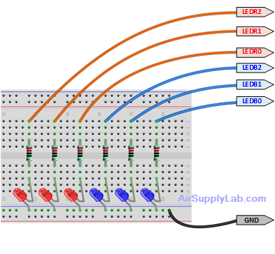
Circuit Diagram
- Position the six LEDs on your breadboard, and pair each one with a 220-ohm resistor. These resistors ensure safe current levels for the LEDs, preventing potential damage.
- Link every LED-resistor combo to a digital output terminal on the microcontroller.
- Attach the push button switch to a digital input on the microcontroller, configuring the pins to function in input mode with an accompanying pull-up resistor.
Pin configurations
| Device | Port.Pin | Signal Type | Module | Direction | Drive Mode |
|---|---|---|---|---|---|
Example Firmware Code
Lab Template Firmware Source Code
This section provides the template firmware source code for the TM4C123G and TM4C1294 platforms used in these laboratory exercises. Explanatory notes are included to help readers understand the purpose and operation of each major part of the program.
The provided code is intended as a reference starting point and may be copied into the project as needed. Since the template is not a final, complete program, it should be reviewed and modified to meet the requirements of each experiment. Unnecessary statements may be commented out, and appropriate comments should be added to clearly document the program structure and implementation details.
EK-TM4C123GXL LaunchPad - main.c
#include <stdio.h>
#include <stdlib.h>
#include <stdint.h>
#include <stdbool.h>

#include "TM4C123GH6PM.h"
#include "MyDefines.h"

void DelayMs(int ms);   // Software Delay Function
void Setup_GPIO(void);
void PoliceLED(uint8_t leds);

//------------------------------------------------------------------------------
int main(void)
{
    // Place your initialization/startup code here (e.g. Setup_GPIO() )
    Setup_GPIO();

    while (1) {
        // Place your application code here

    }
}
//------------------------------------------------------------------------------
/*
Device      Port.Pins       DIR     DriveMode
LEDB0
LEDB1
LEDB2
LEDR0
LEDR1
LEDR2
SW1

Port ____
*/

void Setup_GPIO(void)
{
    // Configure GPIOs
    // 1. Enable Clock to the GPIO Modules (SYSCTL->RCGCGPIO |= (_PORTs);)
    SYSCTL->RCGCGPIO |= (__);
    // allow time for clock to stabilize (SYSCTL->PRGPIO & (_PORTs))
    while ((SYSCTL->PRGPIO & (__)) != (__)) {};
    // 2. Unlock GPIO only PD7, PF0 on TM4C123G; PD7, PE7 on TM4C1294 (GPIOx->LOCK = 0x4C4F434B; and GPIOx->CR = _PINs;)
    //GPIOF->LOCK = 0x4C4F434B;   // Unlock for GPIOF
    //GPIOF->CR |= _PIN0;         // Commit for PIN0
    // 3. Set Analog Mode Select bits for each Port (GPIOx->AMSEL = _PINs;)
    // 4. Set Port Control Register for each Port (GPIOx->PCTL = PMCn << _PTCL_PINn, check the PCTL table)
    // 5. Set Alternate Function Select bits for each Port (GPIOx->AFSEL = _PINs;)
    // 6. Set Output pins for each Port (Direction of the Pins: GPIOx->DIR = _PINs;)

    // 7. Set PUR bits (internal Pull-Up Resistor), PDR (Pull-Down Resistor), ODR (Open Drain) for each Port
    // 8. Set Digital ENable register on all port.pins (GPIOx->DEN = _PINs;)

}
//------------------------------------------------------------------------------
// Delay ms milliseconds (4167:50MHz TM4C123G CPU, 1605:16MHz TM4C123G CPU Clock)
void DelayMs(int ms)
{
    volatile int i, j;
    for (i = 0; i < ms; i++)
        for (j = 0; j < 4167; j++) {} // Do nothing for 1ms
}
//------------------------------------------------------------------------------
void PoliceLED(uint8_t leds)
{

}
//------------------------------------------------------------------------------
EK-TM4C1294XL LaunchPad - main.c
#include <stdio.h>
#include <stdlib.h>
#include <stdint.h>
#include <stdbool.h>

#include "TM4C1294NCPDT.h"
#include "MyDefines.h"

void DelayMs(int ms);   // Software Delay Function
void Setup_GPIO(void);
void PoliceLED(uint8_t leds);

//------------------------------------------------------------------------------
int main(void)
{
    // Place your initialization/startup code here (e.g. Setup_GPIO() )
    Setup_GPIO();
    while (1) {
        // Place your application code here

    }
}
//------------------------------------------------------------------------------
/*
Device      Port.Pins       DIR     DriveMode
LEDB0
LEDB1
LEDB2
LEDR0
LEDR1
LEDR2
SW1

Port ____
*/
void Setup_GPIO(void)
{
    // Configure GPIOs
    // 1. Enable Clock to the GPIO Modules (SYSCTL->RCGCGPIO |= (_PORTs);)
    SYSCTL->RCGCGPIO |= (__);
    // allow time for clock to stabilize (SYSCTL->PRGPIO & (_PORTs))
    while ((SYSCTL->PRGPIO & (__)) != (__)) {};
    // 2. Unlock GPIO only PD7, PF0 on TM4C123G; PD7, PE7 on TM4C1294 (GPIOx->LOCK = 0x4C4F434B; and GPIOx->CR = _PINs;)
    // 3. Set Analog Mode Select bits for each Port (GPIOx->AMSEL = _PINs;)
    // 4. Set Port Control Register for each Port (GPIOx->PCTL = PMCn << _PTCL_PINn, check the PCTL table)
    // 5. Set Alternate Function Select bits for each Port (GPIOx->AFSEL = _PINs;)
    // 6. Set Output pins for each Port (Direction of the Pins: GPIOx->DIR = _PINs;)

    // 7. Set PUR bits (internal Pull-Up Resistor), PDR (Pull-Down Resistor), ODR (Open Drain) for each Port
    // 8. Set Digital ENable register on all port.pins (GPIOx->DEN = _PINs;)

}
//------------------------------------------------------------------------------
// Delay ms milliseconds (1605: 16MHz TM4C1294 CPU Clock)
void DelayMs(int ms)
{
    volatile int i, j;
    for (i = 0; i < ms; i++)
        for (j = 0; j < 1605; j++) {}   // // Do nothing for 1ms
}
//------------------------------------------------------------------------------
void PoliceLED(uint8_t leds)
{

}
//------------------------------------------------------------------------------
Implementation
You are tasked with crafting a minimum of three distinctive police LED light sequences. Consider utilizing a struct to structure the LED sequence as demonstrated::
typedef struct LEDPAT{
    uint8_t leds;
    uint8_t duration;
} LEDPAT;
Structure three pattern arrays as shown:
LEDPAT Pattern1[] = {
                    { , }, // First item
                    ...
};
LEDPAT Pattern2[] = {
                    { , }, // First item
                    ...
};
LEDPAT Pattern3[] = {
                    { , }, // First item
                    ...
};
Within the "main()" function, iterate through your pattern arrays. Illuminate the LEDs as directed by the "leds" parameter in the pattern, and introduce a pause (in milliseconds) as dictated by the "duration" parameter. When the switch (SW1) is activated, shift to the subsequent pattern. Employ software edge-detection techniques to ascertain SW1's state.
Note: Feel free to modify LED sequences and their respective durations to suit your preferences.