Tiva Lab 04: LED Dice

Objective
- To design and program an electrical LED dice using a microcontroller and 7 LEDs
Design and write the program in the embedded system that generates a random number between 1 and 6 (inclusive) when a push button is pressed, and displays the corresponding number of dots on the 7 LEDs for 2 seconds. You can use a pseudo-random number generator and a switch-case statement to map the numbers to the LEDs. For example, 1 can be shown as the center dot, 2 as the opposite dots, 3 as a diagonal line, 4 as a square, 5 as a cross, and 6 as a hexagon. You may also add other features like sound, animation, or delay to enhance the user experience.
Required Reading Materials
- Lesson 07: Create an ARM C Application with Keil μVision MDK-ARM
- Lesson 09: GPIO Ports and Configurations
- Set, Clear, Toggle, and Check Bit Value in C
- Polling Method in Embedded Programming
Components Required
- Microcontroller board (such as PSoC board, TI TIVA board, or similar)
- Breadboard and jumper wires
- 7 LEDs (2 yellows, 2 green LEDs, 2 blue LEDs, and one red LED)
- 11 220-ohm resistors
- An L293 TTL Chip (Datasheet)
| Component/Device | Description | Quantity |
|---|---|---|
| 220 Ω (red red brn gld / red red blk blk brn) | × 11 | |
| Red LED | × 1 | |
| Green LED | × 2 | |
| Blue LED | × 2 | |
| Yellow LED | × 2 | |
| L293D Quadruple Half-H Drivers | × 1 |
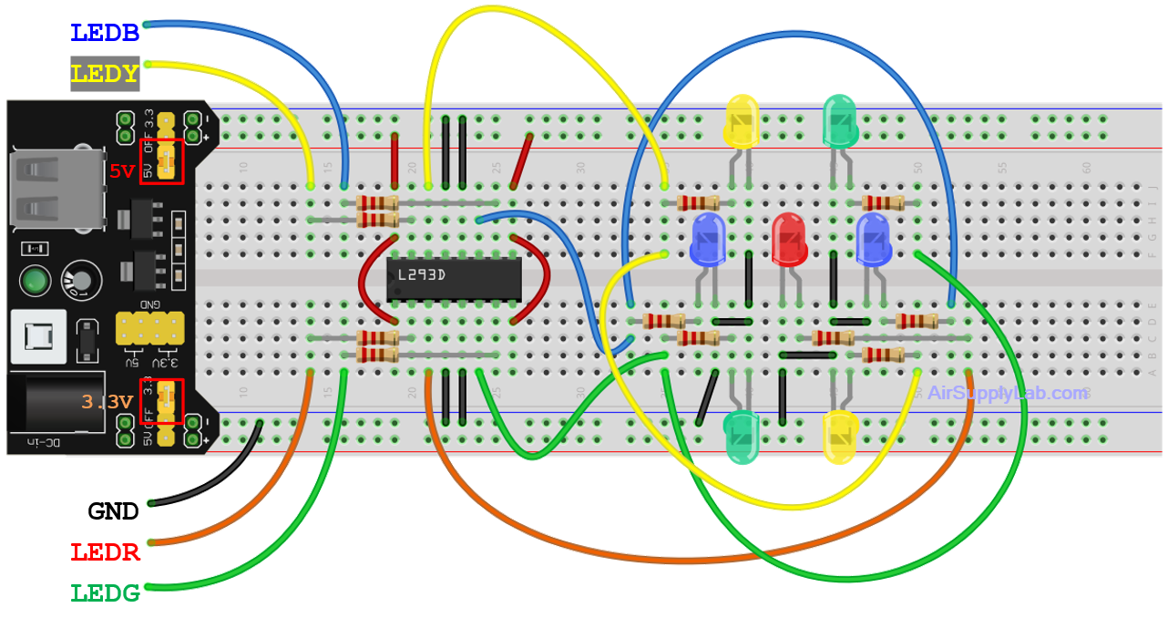
Circuit Diagram
- Insert the 7 LEDs on the breadboard to form a dice diagram, as shown above. Connect each LED to a 220-ohm resistor. The resistors limit the current flowing through the LEDs and protect them from damage due to overcurrent.
- Connect each LED-resistor pair to an output pin of the L293D chip, as shown in the diagram.
- Connect pins LEDR, LEDG, LEDB, and LEDY to the microcontroller. Ensure that these pins are set to output mode in the program.
Safety Tips:
- Do not connect the LEDs directly to the digital pins without resistors.
- Disconnect the power cable (including the USB on the microcontroller board) before making any changes to the circuit.
Pin configurations
| Device | Port.Pin | Signal Type | Module | Direction | Drive Mode |
|---|---|---|---|---|---|
Procedure
- Start a new project in your IDE and create a folder named "003_LED_Dice".
- Include the necessary header files.
- Define the pins for 4 pairs of LEDs and a push button. Ensure that the LEDs' pins are set to output mode, and that the button pin is set to input mode with a pull-up or pull-down resistor.
- Start with the dice displaying a value of 1
- Increment the displayed dice value to the next value. After reaching 6, reset to 0.
- If the push button (SW1) is pressed, display the dice value every 100ms.
- If the button is released, display the dice value every 200 ms for a duration of (1000 + random value) ms. The random value should range from 100 to 1000.
- Continuously check if the button is pressed again and repeat steps 5 to 7 accordingly.
Lab Template Firmware Source Code
This section provides the template firmware source code for the TM4C123G and TM4C1294 platforms used in these laboratory exercises. Explanatory notes are included to help readers understand the purpose and operation of each major part of the program.
The provided code is intended as a reference starting point and may be copied into the project as needed. Since the template is not a final, complete program, it should be reviewed and modified to meet the requirements of each experiment. Unnecessary statements may be commented out, and appropriate comments should be added to clearly document the program structure and implementation details.
EK-TM4C123GXL LaunchPad - main.c
EK-TM4C1294XL LaunchPad - main.c
Programming Tips:
- To detect the state of SW1, consider using software edge-detection methods that trigger an action when the button's state changes from pressed to released, or vice versa. For example:
- When SW1 is pressed, new dice values are displayed every 100 ms.
- When SW1 is released, display new dice values every 200 ms for 1 ~ 3 seconds (1000 ms + a random value), then stop.
typedef enum DICE_LED{
    _LEDR,
    _LEDG,
    _LEDY,
    _LEDB
} DICE_LED;

DICE_LED dice[] = {
    _LEDR,                      // for dice value 1
    _LEDY,                      // for dice value 2
    _LEDR | _LEDY,              // for dice value 3
    _LEDY | _LEDG,              // for dice value 4
    _LEDY | _LEDG | _LEDR,      // for dice value 5
    _LEDY | _LEDG | _LEDB       // for dice value 6
};