Page 31 - EE2449_TTL_Datasheet
P. 31

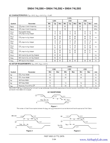
SN54/74LS90 • SN54/74LS92 • SN54/74LS93


           AC CHARACTERISTICS (T A  = 25°C, V CC  = 5.0 V, C L  = 15 pF)
                                                                            Limits
                                                            LS90             LS92             LS93
             Symbol              Parameter             Min   Typ  Max   Min   Typ  Max   Min  Typ   Max   Unit
            f MAX     CP 0  Input Clock Frequency      32               32               32               MHz
            f MAX     CP 1  Input Clock Frequency      16               16               16               MHz
            t PLH     Propagation Delay,                     10    16         10    16         10   16     ns
            t PHL     CP 0  Input to Q 0  Output             12    18         12    18         12   18
            t PLH                                            32    48         32    48         46   70
                      CP 0  Input to Q 3  Output                                                           ns
            t PHL                                            34    50         34    50         46   70
            t PLH                                            10    16         10    16         10   16
                      CP 1  Input to Q 1  Output                                                           ns
            t PHL                                            14    21         14    21         14   21
            t PLH                                            21    32         10    16         21   32
                      CP 1  Input to Q 2  Output                                                           ns
            t PHL                                            23    35         14    21         23   35
            t PLH                                            21    32         21    32         34   51
                      CP 1  Input to Q 3  Output                                                           ns
            t PHL                                            23    35         23    35         34   51
            t PLH     MS Input to Q 0  and Q 3  Outputs      20    30                                      ns
            t PHL     MS Input to Q 1  and Q 2  Outputs      26    40                                      ns
            t PHL     MR Input to Any Output                 26    40         26    40         26   40     ns
           AC SETUP REQUIREMENTS (T A  = 25°C, V CC  = 5.0 V)
                                                                            Limits
                                                           LS90             LS92              LS93
             Symbol             Parameter              Min      Max      Min     Max      Min     Max     Unit
            t W       CP 0  Pulse Width                 15               15               15               ns
            t W       CP 1  Pulse Width                 30               30               30               ns
            t W       MS Pulse Width                    15                                                 ns
            t W       MR Pulse Width                    15               15               15               ns
            t rec     Recovery Time MR to CP            25               25               25               ns
           RECOVERY TIME (t rec ) is defined as the minimum time required between the end of the reset pulse and the clock transition from HIGH-to-LOW in order to recognize
           and transfer HIGH data to the Q outputs
                                                      AC WAVEFORMS

                                        *CP   1.3 V          1.3 V     1.3 V
                                                                t W
                                              t PHL                         t PLH
                                         Q         1.3 V                   1.3 V
                                                          Figure 1
                   *The number of Clock Pulses required between the t PHL  and t PLH  measurements can be determined from the appropriate Truth Tables.


              MR & MS  1.3 V          1.3 V                         MS    1.3 V           1.3 V
                                t W    t rec                                       t W     t rec
                  CP                        1.3 V                    CP                         1.3 V
                       t PHL                                              t PLH
                                                                 Q 0  • Q 3
                  Q               1.3 V                            (LS90)            1.3 V
                              Figure 2                                             Figure 3


                                                  FAST AND LS TTL DATA
                                                           5-94
                                                                                          www.AirSuplyLab.com
                                                                                          www.AirSuplyLab.com
   26   27   28   29   30   31   32   33   34   35   36